hmmwv-manuals
Chapter 7 Brake System Maintenance
| Chapter 8 | TASK SUMMARY |
|---|---|
| TASK | PROCEDURES |
| 7-1 | Parking Brake System Maintenance Task Summary |
| 7-2 | Parking Brake Adjustment |
| 7-3 | Parking Brake Caliper And Rotor Maintenance |
| 7-4 | Parking Brake Lever Replacement |
| 7-5 | Parking Brake Cable Replacement |
| 7-6 | Parking Brake Rod Replacement |
| 7-7 | Parking Brake Heat Shield Replacement |
| 7-8 | Parking Brake Heat Shield And Heat Shield Extension Replacement |
| 7-9 | Service Brake System Bleeding Instructions |
| 7-10 | Service Brake Pad Maintenance |
| 7-11 | Service Brake Caliper Maintenance |
| 7-12 | Master Cylinder Maintenance |
| 7-13 | Master Cylinder Maintenance (Cont'D) |
| 7-14 | Hydro-Boost Replacement |
| 7-15 | Brake Lines Replacement |
| 7-16 | Service Brake Pedal (12338394) Replacement |
| 7-17 | Service Brake Pedal (Ex 5935037) Replacement |
| 7-18 | Proportioning Valve Replacement |
| 7-19 | Service Brake Rotor Replacement |
| 7-20 | REAR DUAL SERVICE/PARKING BRAKE SYSTEM MAINTENANCE TASK SUMMARY |
| 7-21 | Rear Dual Service/Parking Brake Pad Maintenance |
| 7-22 | Rear Dual Service/Parking Brake Caliper Maintenance |
| 7-23 | Right Parking Brake Cable Replacement |
| 7-24 | Left Parking Brake Cable/Mounting Bracket Replacement** |
| 7-25 | Rear Dual Service/Parking Brake Rod Replacement |
| 7-26 | Rear Dual Service/Parking Brake Adjustment |
Section I. Parking Brake System Maintenance
7-1. Parking Brake System Maintenance Task Summary
| Tools | Manual References |
|---|---|
| General mechanic's tool kit: automotive (Appendix B, Item 1) | TM 9-2320-280-10 TM 9-2320-280-24P |
| Materials/Parts | Equipment Condition |
| Cotter pin (Appendix G, Item 14) | Wheel removed (para. 8-3). |
| Locknut (Appendix G, Item 89) | |
| a. Removal | |
| 1. | Remove cotter pin (7), slotted nut (6), and washer (5) from radius rod (4) and geared hub (8). |
| Discard cotter pin (7). | |
| 2. | Remove locknut (9), washer (2), capscrew (1), washer (2), and radius rod (4) from bracket (3) and |
| geared hub (8). Discard locknut (9). | |
| b. Installation | |
| 1. | Install radius rod (4) to bracket (3) with washer (2), capscrew (1), washer (2), and locknut (9). |
7-2. Parking Brake Adjustment
This task covers: Brake Adjustment INITIAL SETUP: Tools General mechanic's tool kit: automotive (Appendix B, Item 1) Materials/Parts Cotter pin (Appendix G, Item 12) Cotter pin (Appendix G, Item 21) Personnel Required One mechanic One assistant Manual References TM 9-2320-280-10 TM 9-2320-280-24P Equipment Condition Wheels chocked and parking brake released (TM 9-2320-280-10).
The following procedure applies to vehicles with serial numbers USBL Eff. 1 through 44824.
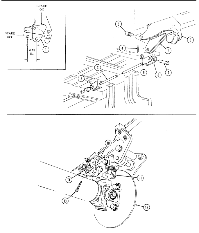
Brake Adjustment 1. Remove clip (5) and open boot (6) to allow access to clevis pin (7). Remove cotter pin (4), washer (9), and clevis pin (7) securing clevis (8) to bellcrank (1). Discard cotter pin (4).
- Remove cotter pin (13) from slotted nut (14). Discard cotter pin (13).
Total gauge thickness should not exceed 0.020 in. (0.508 mm).
-
Place 0.020 in. (0.508 mm) thickness gauge between rotor (12) and brake pad (11). 4. Adjust slotted nut (14) until thickness gauge is snug, and cam (10) is at 11 o'clock position. Install cotter pin (13) in slotted nut (14).
-
Repeatedly apply and adjust parking brake lever until bellcrank (1) linear travel is 0.75 in. (19 mm).
Ensure slack is removed from parking brake linkage.
-
Release parking brake lever and adjust clevis (8) so clevis pin (7) slides easily into bellcrank (1) and secure with washer (9) and cotter pin (4). If alignment cannot be made at clevis (8), adjust rod (3) in or out of rear clevis (2) to obtain proper alignment.
-
Remove thickness gauge. 8. Close boot (6) and secure with clip (5).
Apply parking brake lever gradually, while burnishing brakes, to bring vehicle to a gradual stop. Sudden or quick application of brake lever can damage parking brake rotor.
Perform steps 9-11 only if parking brake pads were replaced.
-
Burnish parking brake pads (11) by operating vehicle at 10 mph (16 kph) and, using the parking brake, slow down and bring the vehicle to a gradual stop. Allow parking brake rotor (12) to cool by operating vehicle 2.5 miles (4 km) at 20 mph (32 kph). Repeat this step ten times.
-
Remove parking brake rotor (12) (para. 7-3.a) and inspect brake pads (11) for a large contact pattern across the surface of the brake pads (11). If contact pattern is not a minimum of 90%, install parking brake rotor (12) (para. 7-3.c) and repeat step 9. If contact pattern is satisfactory, install parking brake rotor (para. 7-3.c) and go to step 11.
-
Readjust, following steps 1 through 8.
FOLLOW-ON TASK: Check parking brake for proper operation (TM 9-2320-280-10).
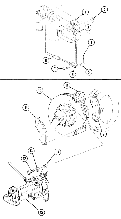
7-3. Parking Brake Caliper And Rotor Maintenance
This task covers: b. Inspection INITIAL SETUP: Tools General mechanic's tool kit: automotive (Appendix B, Item 1)
Materials/Parts
Four lockwashers (Appendix G, Item 134) Two lockwashers (Appendix G, Item 178) Cotter pin (Appendix G, Item 12) Cotter pin (Appendix G, Item 21) Four gaskets (Appendix G, Item 59) Two locknuts (Appendix G, Item 70) Sealing compound (Appendix C, Item 45) Grease (Appendix C, Item 22) a. Removal c. Installation Personnel Required One mechanic One assistant Manual References TM-9-2320-280-10 TM 9-2320-280-24P Equipment Condition Wheels chocked and parking brake released (TM 9-2320-280-10)
The following procedure applies to vehicles with serial numbers USBL Eff. 1 through 44824.
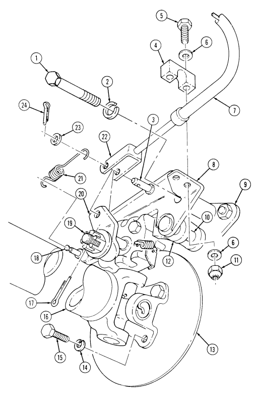
a. Removal 1. Remove four capscrews (15) and lockwashers (14) from rear propeller shaft (16) and parking brake rotor (13). Disconnect rear propeller shaft (16) and remove rotor (13). Discard lockwashers (14).
- Remove cotter pin (17) from slotted nut (19), and loosen slotted nut (19). Discard cotter pin (17). 3. Remove cotter pin (24), washer (23), spring (21), clevis pin (3), and clevis (22) from cam (20).
Remove spring (21) from pin post (18). Discard cotter pin (24).
-
Remove two locknuts (11), washers (6), capscrews (5), washers (6), and clamp (4) from parking brake cable (7) and plate and guide pin assembly (8). Discard locknuts (11).
-
Remove two capscrews (1) and lockwashers (2) from plate and guide pin assembly (8) and caliper mounting bracket (9). Discard lockwashers (2).
-
Slide plate and guide pin assembly (8) towards front of vehicle until pins (10) come out of bracket (9).
-
Remove plate and guide pin assembly (8) and caliper assembly (12).
7-3. PARKING BRAKE CALIPER AND ROTOR MAINTENANCE (Cont'd)
-
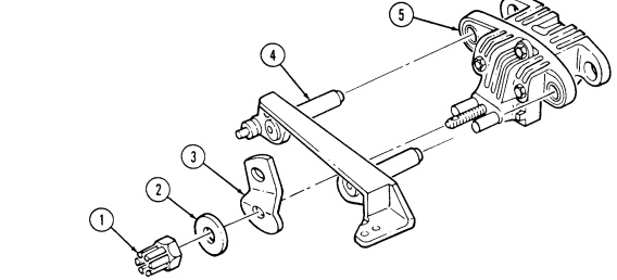
Remove slotted nut (1), washer (2), and cam (3) from caliper (50). 9. Remove plate and guide pin assembly (4) from caliper (5).
-
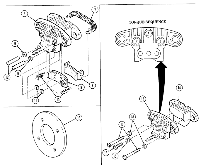
Remove two push pins (12) and two gaskets (6) from caliper (5). Discard gaskets (6). 11. Remove spring (7) and rear brake pad (8) from caliper half (14). 12. Remove two springs (10), front brake pad (9), and two gaskets (11) from caliper half (13). Discard gaskets (11).
-
If caliper (5) requires disassembly, remove two long capscrews (17), washers (18), short capscrew (16), and washer (15). Separate caliper halves (13) and (14).
B. Inspection
-
Inspect caliper halves (13) and (14) for cracks, wear, elongated holes, and bends. Replace as necessary.
-
Inspect rotor (19) for cracks, wear, elongated holes, and warping. Replace if defective, or rotor thickness is less than 5/32 in. (4 mm).
-
Inspect brake pads (9) and (8) for wear. If brake pad thickness is less than 1/8 in. (3.2 mm), replace both pads (9) and (8). Replace both pads (9) and (8) if rotor (19) was replaced.
C. Installation
-
If caliper halves (13) and (14) require assembly, apply sealing compound to threads of capscrews (17) and (16). Install caliper halves (13) and (14) with washer (15), short capscrew (16), two washers (18), and two long capscrews (17). Tighten capscrews (17) and (16) in sequence shown, to 30-35 lb-ft (41-47 N•m).
-
Install two gaskets (11) and front brake pad (9) on caliper (5) with two springs (10). 3. Install long spring (7) on rear brake pad (8). 4. Install rear brake pad (8) on caliper (5) with spring (7). 5. Clean and lubricate push pins (12), cam-to-push pin contact area, and push pin openings in caliper (5) with grease.
-
Install two gaskets (6) and push pins (12) in caliper (5) with rounded ends of push pins (12) facing outward.
-
Install plate and guide pin assembly (4) on caliper (5). 8. Install cam (3) on caliper (5) with washer (2) and slotted nut (1). Do not tighten slotted nut (1).
Note
Avoid placing parking brake cable behind mounting bracket when performing step 9.
Install caliper (11) and plate and guide-pin assembly (8) on caliper mounting bracket (9).
Apply sealing compound to threads of capscrews (2). Install plate and guide pin assembly (8) to caliper mounting bracket (9) with two lockwashers (3) and capscrews (2). Tighten capscrews (2) to 90 lb-ft (122 Nom). Install parking brake cable (7) on plate and guide pin assembly (8) with clamp (4), two washers (5), capscrews (6), washers (5), and locknuts (10). Tighten locknuts (10) to 5 lb-ft (7 Nd).
Position rotor (12) to caliper (11). Install clevis (19) to cam (17) with clevis pin (20), long end of spring (18), washer (21), and cotter pin (l). Install short end of spring (18) on pin post (16) and crimp short end of spring (18) with pliers. Install rear propeller shaft (15) to rotor (12) with four lockwashers (13) and capscrews (14). Tighten capscrews (14) to 60 lb-ft (81 N*m).
7-3. PARKING BRAKE CALIPER AND ROTOR MAINTENANCE (Cont'd)
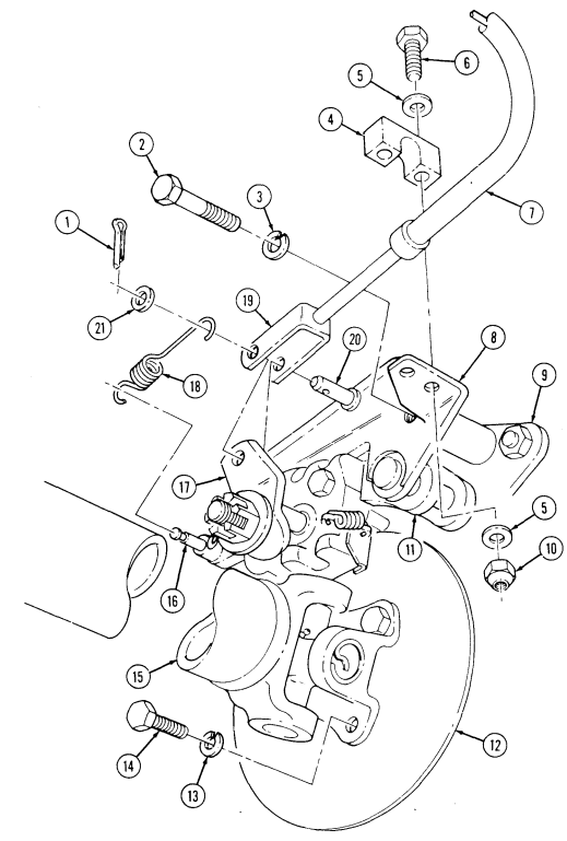
FOLLOW-ON TASK: Adjust parking brake (para. 7-2).
7-4. Parking Brake Lever Replacement
This task covers: INITIAL SETUP:
Tools
General mechanic's tool kit: automotive (Appendix B, Item 1) Materials/Parts Two assembled locknuts (Appendix G, Item 131) Five locknuts (Appendix G, Item 71) Cotter pin (Appendix G, Item 12) Personnel Required One mechanic One assistant
A. Removal B. Installation
Manual References TM-9-2320-280-10 TM 9-2320-280-24P Equipment Condition - Wheels chocked and parking brake released (TM 9-2320-280-10).
- Parking brake switch removed (para. 4-19).
A. Removal
-
Remove clip (1) and open boot (2) to allow access to clevis pin (4). 2. Remove cotter pin (7), washer (6), and clevis pin (4) from clevis (5) and bellcrank (3). Discard cotter pin (7).
-
Remove assembled locknut (9), wiring harness clamp (10), assembled locknut (9) and capscrew (19) from parking brake lever (8). Discard assembled locknut (9).
-
Remove three locknuts (11), washers (12), and capscrews (17) from parking brake lever (8) and body (20). Discard locknuts (11).
-
Remove two locknuts (16), washers (15), capscrews (13), washers (14), and parking brake lever (8) from body (20). Discard locknuts (16).
-
Remove upper boot (18) from parking brake lever (8). 7. Remove lower boot (2) from body (20).
B. Installation
-
Install lower boot (2) on body (20). 2. Install upper boot (18) on parking brake lever (8). 3. Install parking brake lever (8) on body (20) with two washers (14), capscrews (13), washers (15), and locknuts (16).
-
Secure parking brake lever (8) on body (20) with capscrew (19), assembled locknut (9), wiring harness clamp (10), and assembled locknut (9).
-
Secure parking brake lever (8) on body (20) with three capscrews (17), washers (12), and locknuts (11).
-
Install clevis (5) on bellcrank (3) with clevis pin (4), washer (6), and cotter pin (7). 7. Apply parking brake lever (8) and tighten capscrews (13), (17), and (19) to 8 lb-ft (11 N•m).
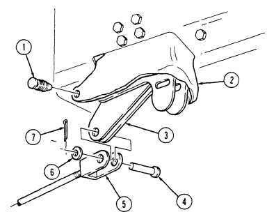
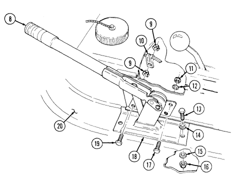
FOLLOW-ON TASKS: - Install parking brake switch (para. 4-19).
- Adjust parking brake (para. 7-2).
7-5. Parking Brake Cable Replacement
This task covers: INITIAL SETUP:
Tools
General mechanic's tool kit: automotive (Appendix B, Item 1) Materials/Parts Two cotter pins (Appendix G, Item 12) Cotter pin (Appendix G, Item 21) Two locknuts (Appendix G, Item 70) Four lockwashers (Appendix G, Item 143) a. Removal b. Installation Manual References TM 9-2320-280-10 TM 9-2320-280-24P Equipment Condition
-
Wheels chocked and parking brake released (TM 9-2320-280-10).
-
Muffler and insulator removed (para. 3-48).
The following procedure applies to vehicles with serial numbers USBL Eff. 1 through 44824.
A. Removal
-
Remove four capscrews (10) and lockwashers (9) and disconnect rear propeller shaft (11) from parking brake rotor (8). Discard lockwashers (9).
-
Remove cotter pin (12) and loosen slotted nut (14). Discard cotter pin (12). 3. Remove cotter pin (17), washer (16), spring (15), clevis pin (20), and clevis (18) from cam (19).
Remove spring (15) from pin post (13). Discard cotter pin (17).
-
Remove two locknuts (7), washers (6), capscrews (23), washers (6), and clamp (22) from brake cable (5) and plate and guide pin assembly (21). Discard locknuts (7).
-
Remove cotter pin (3), washer (4), and clevis pin (1) from brake cable (5) and brake rod clevis (2).
Discard cotter pin (3).
- Remove clip (24) and brake cable (5) from bracket (25).
B. Installation
-
Install brake cable (5) in bracket (25) with clip (24). 2. Install brake rod clevis (2) on brake cable (5) with clevis pin (1) washer (4), and cotter pin (3). 3. Install brake cable (5) on plate and guide pin assembly (21) with clamp (22), two washers (6), capscrews (23), washers (6), and locknuts (7). Tighten locknuts (7) to 5 lb-ft (7 N•m).
-
Install short end of spring (15) onto pin post (13) and crimp short end of spring (15). 5. Install cable clevis (18) to cam (19) with clevis pin (20), long end of spring (15), washer (16), and cotter pin (17).
-
Connect rear propeller shaft (11) to rotor (8) with four lockwashers (9) and capscrews (10). Tighten capscrews (10) to 60 lb-ft (81 N•m).
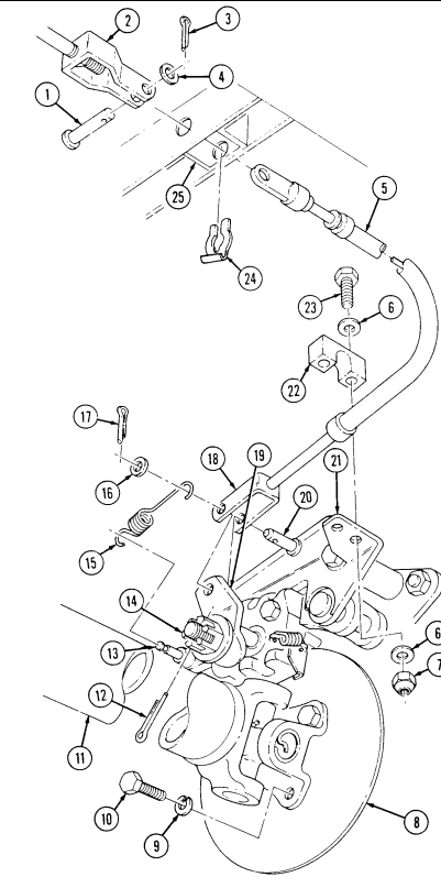
FOLLOW-ON TASKS: - Install muffler and insulator (para. 3-48).
- Adjust parking brake (para. 7-2).
7-6. Parking Brake Rod Replacement
This task covers: INITIAL SETUP: Tools General mechanic's tool kit: automotive (Appendix B, Item 1) Materials/Parts Two cotter pins (Appendix G, Item 12) Locknut (Appendix G, Item 79) Manuals/References TM 9-2320-280-10 TM 9-2320-280-24P a. Removal b. Installation Equipment Condition
-
Wheels chocked and parking brake released (TM 9-2320-280-10).
-
Muffler and insulator removed (para. 3-48).
The following procedure applies to vehicles with serial numbers USBL Eff. 1 through 44824.
a. Removal
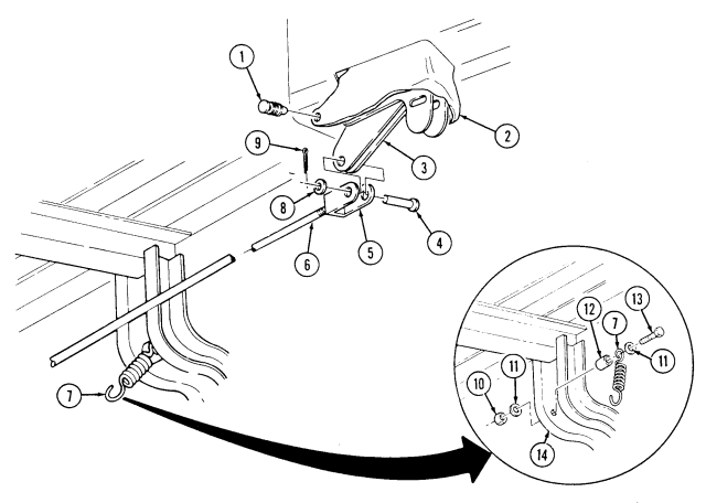
- Remove clip (1) and open boot (2) to allow access to clevis pin (4).
- Remove cotter pin (9), washer (8), and clevis pin (4) from clevis (5) and bellcrank (3). Discard cotter pin (9).
- Disconnect spring (7) from brake rod (6).
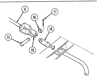
- Remove cotter pin (17), washer (16), clevis pin (15), and brake rod (6) from brake cable (18). Discard cotter pin (17).
- Remove clevis (5) and clevis (19) from brake rod (6).
Perform steps 6 and 7 if replacing spring. If not replacing spring, go to b., installation. 6. Remove locknut (10), washer (11), capscrew (13), washer (11), spring (7), and spacer (12) from body (14). Discard locknut (10). 7. Install spacer (12) and spring (7) to body (14) with washer (11), capscrew (13), washer (11), and locknut (10).
B. Installation
- Install clevis (5) and clevis (19) on brake rod (6).
- Install brake rod (6) to brake cable (18) with clevis pin (15), washer (16), and cotter pin (17).
- Install clevis (5) on bellcrank (3) with clevis pin (4), washer (8), and cotter pin (9).
- Connect spring (7) to brake rod (6).
- Close boot (2) and install clip (1).
FOLLOW-ON TASKS: - Install muffler and insulator (para. 3-48).
- Adjust parking brake (para. 7-2).
7-7. Parking Brake Heat Shield Replacement
This task covers: INITIAL SETUP: Tools General mechanic's tool kit: automotive (Appendix B, Item 1) a. Removal b. Installation Manual Referneces TM 9-2320-280-24P Materials/Parts Two lockwashers (Appendix G, Item 135)
The following procedure applies to vehicles with serial numbers USBL Eff. 1 through 44824.
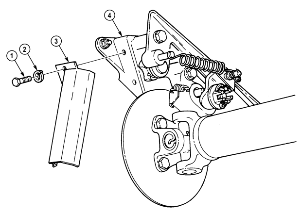
a. Removal Remove two capscrews (1), lockwashers (2), and heat shield (3) from parking brake bracket (4). Discard lockwashers (2).
b. Installation Install heat shield (3) to parking brake bracket (4) with two lockwashers (2) and capscrews (1). Tighten capscrews (1) to 6 lb-ft (8 N•m).
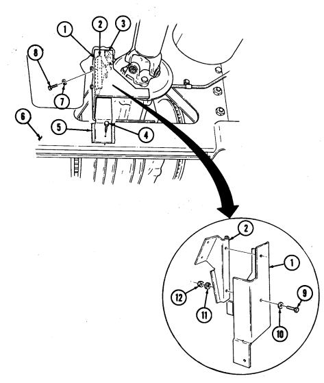
7-8. Parking Brake Heat Shield And Heat Shield Extension Replacement
This task covers: INITIAL SETUP:
Tools
General mechanic's tool kit: automotive (Appendix B, Item 1)
Materials/Parts
Four lockwashers (Appendix G, Item 138) Felt sheet (Appendix D, Fig. 84) Heat shield extension (Appendix D, Fig. 85) a. Removal b. Installation Manual References TM 9-2320-280-24P
-
The heat shield extension is used for extra protection of the parking brake. The replacement of it can be left up to the discretion of the commander.
-
The following procedure applies to vehicles with serial numbers USBL Eff. 1 through 44824.
A. Removal
-
Remove two capscrews (8) and lockwashers (7) from heat shield extension (1), heat shield (2) and parking brake bracket (3). Discard lockwashers (7).
-
Remove capscrew (4), heat shield extension (1), and felt sheet (5) from crossmember (6). Discard felt sheet (5).
-
Remove two nuts (12), lockwashers (11), heat shield (2), capscrews (9), and washers (10) from heat
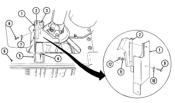
shield extension (1). Discard lockwashers (11).
b. Installation
- Install heat shield (2) to heat shield extension (1) with two washers (10), capscrews (9), lockwashers (11), and nuts (12).
- Install felt sheet (5) and heat shield extension (1) to crossmember (6) with capscrew (4). 3. Install heat shield extension (1) and heat shield (2) on parking brake bracket (3) with two lockwashers (7) and capscrews (8).
7-8.1. Brake Protection Guards Replacement
This task covers:
| Applicable Models |
|---|
| 1155 SECT 100 - 11 11 4 4 4 4 4 4 4 4 4 4 1 4 |
| General mechanic's tool kit: |
|---|
INITIAL SETUP: All M1123 and "A2" series vehicles General mechanic's tool kit: automotive (Appendix B, Item 1)
Materials/Parts
Six locknuts (without 10,500 lb hydraulic winch) (Appendix G, Item 128) Three locknuts (with 10,500 lb hydraulic winch) (Appendix G, Item 128) Six locknuts (Appendix G, Item 79) a. Removal b. Installation a. Removal
| Personnel Required |
|---|
| One mechanic |
| One assistant |
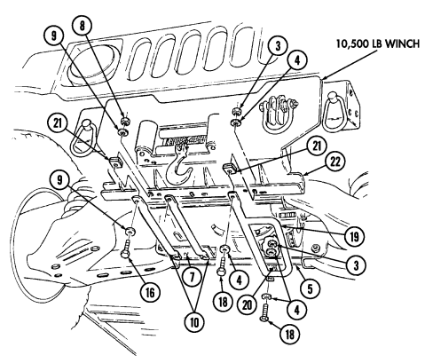
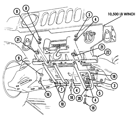
Perform steps 1 through 4 for vehicles equipped with 10,500 lb hydraulic winch only.
-
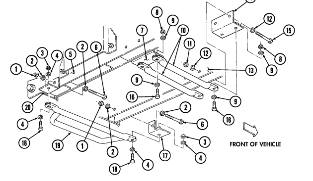
Remove two locknuts (3), washers (4), capscrews (18), washers (4), spacer (21), and left front brake protection guard (19) from bracket (20) and bumper (22). Discard locknuts (3).
-
Remove four locknuts (8), washers (9), capscrews (16), washers (9), two spacers (21), and right front brake protection guards (10) from bracket (7) and bumper (13). Discard locknuts (8).
-
Remove locknut (1), washer (2), capscrew (6), washer (2), and bracket (20) from front rear crossmember (5). Discard locknut (1)
-
Remove two locknuts (11), washers (12), capscrews (15), washers (12), and bracket (7) from front crossmember (5). Discard locknuts (11).
-
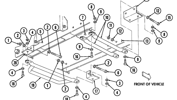
Remove two locknuts (3), washers (4), capscrews (18), washers (4), and left front brake protection guard (19) from brackets (17) and (20). Discard locknuts (3).
-
Remove four locknuts (8), washers (9), capscrews (16), washers (9), and right front brake protection guards (10) from brackets (7) and (14). Discard locknuts (8).
-
Remove two locknuts (1), washers (2), capscrews (6), washers (2), and brackets (17) and (20) from front rear crossmember (5) and front crossmember (13). Discard locknuts (1).
-
Remove four locknuts (11), washers (12), capscrews (15), washers (12), and brackets (7) and (14) from front rear crossmember (5) and front crossmember (13). Discard locknuts (11).
(14)
b. Installation
Perform steps 1 through 4 for vehicles with 10,500 lb hydraulic winch only.
-
Install bracket (20) on front rear crossmember (5) with washer (2), capscrew (6), washer (2), and locknut (1). Tighten capscrew (6) to 378 lb ft (513 N•m).
-
Install bracket (7) on front rear crossmember (5) with two washers (12), capscrews (15), washers (12), and locknuts (11). Tighten capscrews (15) to 378 lb-ft (513 N•m).
-
Install spacer (21) and left front brake protection guard (19) on bumper (22) and bracket (20) with two washers (4), capscrews (18), washers (4), and locknuts (3). Tighten capscrews (18) to 378 lb-ft (513 N•m).
-
Install two spacers (21) and right front brake protection guards (10) on bumper (22) and bracket (7) with four washers (9), capscrews (16), washers (9), and locknuts (8). Tighten capscrews (16) to 378 lb-ft (513 N•m).
-
Install brackets (17) and (20) on front rear crossmember (5) and front crossmember (13) with two washers (2), capscrews (6), washers (2), and locknuts (1). Tighten capscrews (6) to 378 lb-ft (513 N•m).
-
Install brackets (7) and (14) on front rear crossmember (5) and front crossmember (13) with four washers (12), capscrews (15), washers (12), and locknuts (11). Tighten capscrew (15) to 378 lb-ft (513 N•m).
-
Install right front brake protection guards (10) on brackets (7) and (14) with four washers (9), capscrews (16), washers (9), and locknuts (8). Tighten capscrews (16) to 378 lb-ft (513 N•m).
-
Install left front brake protection guard (19) on brackets (17) and (20) with two washers (4), capscrews (18), washers (4), and locknuts (3). Tighten capscrews (18) to 378 lb-ft (513 N•m).
7-8.1. Brake Protection Guards Replacement (Gnt'D)
(14
(18
Section Ii. Service Brake System Maintenance 7-9. Service Brake System Maintenance Task Summary
| a. Removal b. | Installation |
|---|---|
| INITIAL SETUP: | |
| Tools | Manual References |
| General mechanic's tool kit: | TM 9-2320-280-10 |
| automotive (Appendix B, Item 1) | TM 9-2320-280-24P |
| Materials/Parts | Equipment Condition |
| Four locknuts (Appendix G, Item 128) | - Hood raised and secured |
| (Basic/A1 Series) | (TM 9-2320-280-20-10) (front springs only). |
| Four locknuts (Appendix G,Item 105) | M1037 and M1042 only: |
| (A2 Series) | - Shelter removed (para. 11-120) |
| Locknut (Appendix G,Item 106) | (rear shock absorbers only). |
| Sealing compound (Appendix C, Item 40) | - Lower control arm supported (para. 6-29) |
| (rear shock absorbers only). | |
| NOTE | |
| The procedure for removing and installing all four coil springs are | |
| basically the same. This procedure covers the left front coil spring. |
7-10. Service Brake System Bleeding Instructions
This task covers: a. Pressure Bleeding c. Master Cylinder Bleeding b. Manual Bleeding INITIAL SETUP:
| 2. Remove wheel (para. 8-3). on shock pin (2). |
|---|
Tools Manual References
General mechanic's tool kit: TM 9-2320-280-10
automotive (Appendix B, Item 1) TM 9-2320-280-24P
Materials/Parts Equipment Condition
One assistant (task b. only) General Safety Instructions
Brake fluid (Appendix C, Item 14) Hood raised and secured (TM 9-2320-280-10).
Master cylinder filled to proper level (para. 2-11, pg 2-12, Item 11).
Always wear eye protection when bleeding brakes.
Warnin G
Always wear eye protection when bleeding brakes. Failure to do this may cause injury if brake fluid comes in contact with eyes.
Note If only the front or rear half of the system has been serviced, it is usually necessary to bleed only that half of the system. However, if a firm brake pedal cannot be obtained after bleeding, it will be necessary to bleed the entire system. The brake hydraulic system can be bled manually or by using a pressure tank and adapters. Each method is outlined in the following procedures.
Bleed brakes in the following order: right rear, left rear, right front, left front.
a. Pressure Bleeding
When using a pressure bleeding tank, follow the manufacturer's instructions for its use. Do not exceed the recommended working pressure when pressurizing the tank. A tank pressure of 15-20 psi (103, 138 kPa) is sufficient to bleed the brake hydraulic system. Release all air pressure from the tank after using it.
After refilling pressure bleeding tank with silicone brake fluid, let tank sit undisturbed for 30 minutes minimum to ensure all visible as well as minute air bubbles are gone.
Note This procedure covers bleeding at one wheel. Repeat bleeding task for remaining wheels.
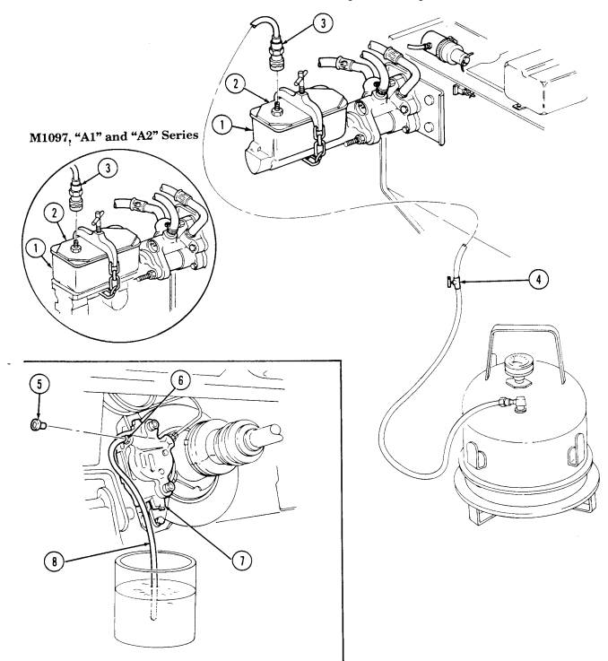
Remove cover from master cylinder (1).
Install pressure tank bleeder adapter (2) to master cylinder (1).
Connect line (3) from pressure tank to adapter (2). Remove protective cap (5) from bleeder screw (6) on caliper assembly (7).
Connect short piece of hose (8) to bleeder screw (6), and place other end of hose (8) in container 3/4 full of brake fluid.
Open valve (4) on line from pressure tank to master cylinder (1), allowing pressurized brake fluid to enter system.
Open bleeder screw (6) 3/4 turn and observe brake fluid in container. Close bleeder screw (6) when brake fluid flows free of air bubbles.
Disconnect hose (8) from bleeder screw (6) and install protective cap (5) on bleeder screw (6). Close valve (4) on line (3) from pressure tank to master cylinder (1). Disconnect line (3) from adapter (2). Remove adapter (2) from master cylinder (1) and install master cylinder cover.
B. Manual Bleeding Note
This procedure covers bleeding at one wheel. Repeat bleeding task for remaining wheels.
Assistant is required to depress the brake pedal when manually bleeding brakes while mechanic opens and closes bleeder screw.
-
Remove protective cap (5) from bleeder screw (6) on caliper assembly (7).
-
Connect short piece of hose (8) to bleeder screw (6), and place other end of hose (8) in container 3/4 full brake fluid.
Check the master cylinder fluid level frequently during the bleeding operation and refill the reservoirs as necessary. Do not allow the master cylinder to run out of fluid at any time, or additional air will be drawn into the system. After adding silicone brake fluid to master cylinder, let cylinder sit undisturbed for 30 minutes minimum to ensure all visible as well as minute air bubbles are gone.
7-10. Service Brake System Bleeding Instructions (Cont'D)
-
Have assistant pump brake pedal toward floor and hold it there. Open bleeder screw (6) 3/4 turn.
-
When pedal reaches floor, tighten bleeder screw (6) and have assistant slowly release brake pedal. 5. Repeat steps 3 and 4 until fluid flows clear and free of air bubbles. 6. Disconnect hose (8) from bleeder screw (6) and install protective cap (5) on bleeder screw (6).
7-10. Service Brake System Bleeding Instructions (Cont'D)
c. Master Cylinder Bleeding
Note
Perform this procedure prior to installing master cylinder on vehicle.
Secure master cylinder flange (5) in vise. Remove cover (1) and fill reservoirs (2) with silicone brake fluid.
Screw threaded end of bleeder hose (3) into brake line port on master cylinder (6) and insert opposite end into reservoir (2). Repeat step for other bleeder hose (3).
Slowly push piston (4) into master cylinder (6). Do not release piston (4). While holding piston (4), pinch bleeder hoses (3) off and release piston (4). Piston (4) will return automatically.
Whenever the master cylinder is filled with silicone brake fluid, let cylinder sit undisturbed for 30 minutes minimum to ensure that all visible as well as minute air bubbles are gone.
Refill reservoirs (2) with silicone brake fluid and repeat step 4 until no air bubbles remain in brake fluid. Remove two bleeder hoses (3) from brake line ports on master cylinder (6). Install cover (1) on master cylinder (6) and remove from vise. Install master cylinder (para. 7-13).
7-10. Service Brake System Bleeding Instructions (Cont'D)
FOLLOW-ON TASKS: Lower and secure hood (TM 9-2320-280-10).
Operate vehicle (TM 9-2320-280-10) and check for proper operation.
7-11 Service Brake Pad Maintenance
This task covers: a. Removal c. Installation b. Cleaning and Inspection INITIAL SETUP: Applicable Models All "A2" series vehicles Tools General mechanic's tool kit: automotive (Appendix B, Item 1) "C" clamp (Appendix B, Item 164) Special Tools Crowfoot, 14 mm (Appendix B, Item 152) Materials/Parts Grease (Appendix C, Item 22) Sealing compound (Appendix C, Item 45)
| TM 9-2320-280-10 |
|---|
| TM 9-2320-280-24P |
TM 9-2320-280-10 TM 9-2320-280-24P Equipment Condition Brake protection guards removed (para. 7-8.1) (M998A2 vehicle only).
General Safety Instructions Make sure brake pads are installed with linings facing rotor.
Note
-
The following procedure applies to the front brake system on all vehicles and to the rear brake system on vehicles with serial numbers USBL Eff. 1 through 44824.
-
For replacement of rear dual service/parking brake pad on vehicles with serial numbers USBL Eff. 44825 and above, refer to para. 7-21)
-
If removing left front brake pads, halfshaft must be removed (para. 6-9).
a. Removal
Caliper must be supported during removal to prevent damage to brake line.
- Using crowfoot, remove two capscrews (7), washers (6), caliper (4), and yoke (5) from adapter (3).
Note Note positioning of brake pad surfaces for installation.
- Remove two brake pads (1) from adapter (3).
B. Cleaning And Inspection
-
Clean mating surfaces of caliper (4) and adapter (3) and lubricate with grease. 2. Inspect caliper (4) and caliper piston (8) for cracks, pitting, or damage. Replace caliper (4) if cracked, pitted, or damaged (para. 7-12).
-
Inspect dust boot (9) for tears or deterioration. Replace caliper (4) if dust boot (9) is torn or deteriorated (para. 7-12).
-
Inspect rotor (2) for heat cracks, discoloration, pitting, or scoring. Replace rotor (2) if cracked, pitted, or scored (para. 7-19).
Note
-
To ensure proper brake function, replace brake pads in pairs on both sides of axle.
-
Replace brake pads if thickness is less than 3/16 in. (4.8 mm) and operation in wet and muddy conditions is expected.
- Inspect brake pads (1) for glazing, oil saturation, or wear. If glazed, oil saturated, or if brake pad thickness is less than 1/8 in. (3.2 mm), replace both pads (1) and pads from opposite caliper.
c. Installation
Ensure brake pads are installed with linings facing rotor. Failure to do this may cause injury to personnel or damage to equipment.
- Position brake pads (1) to adapter (3).
Note
When installing yoke and caliper, use a "C" clamp and a block of wood to bottom out position in caliper if needed.
2 . Apply sealing compound to threads of capscrews (7). Using crowfoot, install yoke (5) and caliper (4) to
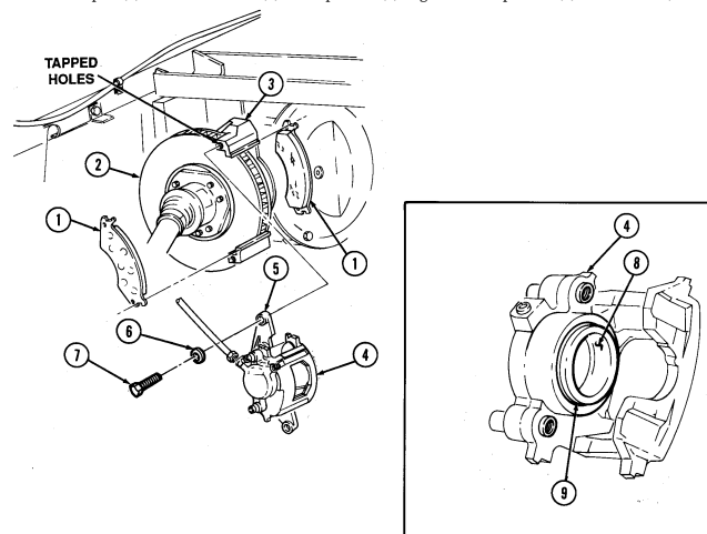
adapter (3) with two washers (6) and capscrews (7). Tighten two capscrews (7) to 30-40 lb-ft (41-54 N.m ) .
FOLLOW-ON TASK: Install brake protection guards (para. 7-8.1) (M998A2 vehicle only).
7-12. Service Brake Caliper Maintenance
This task covers: a. Removal c. Installation b. Cleaning and Inspection INITIAL SETUP: Tools General mechanic's tool kit: automotive (Appendix B, Item 1) "C" clamp (Appendix B, Item 164)
Special Tools
Hex-head driver, 7-mm (Appendix B, Item 162) Crowfoot, 14-mm (Appendix B, Item 152) Materials/Parts Flat washer (Appendix G, Item 38) Grease (Appendix C, Item 22) Sealing compound (Appendix C, Item 45) Manual References TM 9-2320-280-10 TM 9-2320-280-24P Equipment Condition Brake protection guards removed (para. 7-8.1) (M998A2 vehicle only).
General Safety Instructions Make sure brake pads are installed with linings facing rotor.
-
The following procedure applies to the front brake system on all vehicles and to the rear brake system on vehicles with serial numbers USBL Eff. 1 through 44824.
-
For replacement of rear dual service/parking brake pad on vehicles with serial numbers USBL Eff. 44825 and above, refer to para. 7-22.
a. Removal
Cover or plug all open lines and connections immediately after disconnection to prevent contamination. Remove all plugs prior to connection.
- Disconnect brake line (1) from coupling (10). 2. Remove coupling (10) and flat washer (11) from caliper (9). Discard flat washer (11). 3. Using crowfoot, remove two capscrews (7), washers (6), yoke (5), and caliper (9) from adapter (4).
NOTE Note positioning of brake pad surfaces for installation.
- Remove two brake pads (2) from adapter (4). 5. Slide yoke (5) and locating pins (8) out from caliper (9).
B. Cleaning And Inspection
-
Clean mating surfaces of caliper (9) and adapter (4) and lubricate with grease. 2. Clean cooling fins of rotor (3). 3. Inspect caliper (9) and caliper piston (12) for cracks, pitting, or damage. Replace caliper (9) if cracked, pitted, or damaged.
-
Inspect locating pin bearings and bushings (14) for tears or deterioration. Replace bearings and bushings (14) if torn or deteriorated.
-
Inspect dust boot (13) for tears or deterioration. Replace caliper (9) if dust boot (13) is torn or deteriorated.
-
Inspect yoke locating pins (8) for cracks or corrosion. Perform step 7 if pins (8) are cracked or corroded.
-
Using 7-mm hex-head driver, remove locating pins (8) from yoke (5). Discard locating pins (8).
7-26 Change 3
- Inspect rotor (3) for heat cracks, discoloration, pitting, or scoring. Replace rotor (3) if cracked, pitted, or scored (para. 7-19).
- Replace brake pads in sets only. - Replace brake pads if thickness is less than 3/16 in. (4.8 mm) and operation in wet and muddy conditions is expected.
- Inspect brake pads (2) for glazing, oil saturation, or wear. If glazed, oil satruated, or if brake pad thickness is less than 1/8 in. (3.2 mm), replace both pads (2) and pads from opposite caliper (para. 7-11).
c. Installation
Ensure brake pads are installed with linings facing rotor. Failure to do this may cause injury to personnel or damage to equipment.
- Install brake pads (2) on adapter (4).
Perform step 2 only if yoke locating pins were replaced.
- Apply sealing compound to threads of locating pins (8) and install locating pins (8) in yoke (5).
Tighten locating pins (8) to 25-35 lb-ft (34-47 N•m).
- Install caliper (9) on yoke (5).
NOTE When installing caliper, use a "C" clamp and a block of wood to bottom out piston in caliper if needed.
- Apply sealing compound to tapped holes of adapter (4). Using crowfoot, install yoke (5) and
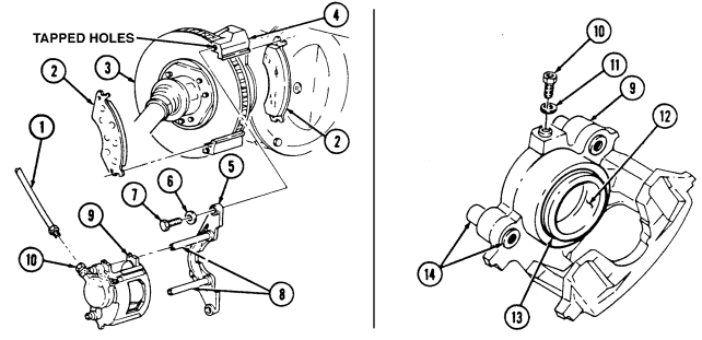
caliper (9) to adapter (4) with two washers (6) and capscrews (7). Tighten two capscrews (7) to 30-40 lb-ft (41-54 N•m).
- Install flat washer (11) and coupling (10) on caliper (9). 6. Connect brake line (1) to coupling (10).
FOLLOW-ON TASKS - Bleed brake system (para. 7-10).
- Install brake protection guards (para. 7-8.1) (M998A2 vehicles only).
7-13. Master Cylinder Maintenance
This task covers: a. Removal c. Bleeding b. Installation INITIAL SETUP: Tools General mechanic's tool kit: automotive (Appendix B, Item 1) Materials Parts Five locknuts (Appendix G, Item 128) Personnel Required One mechanic One assistant a. Removal Manual References TM 9-2320-280-10 TM 9-2320-280-24P Equipment Condition Hood raised and secured (TM 9-2320-280-10).
Cover or plug all open lines and connections immediately after disconnection to prevent contamination. Remove all plugs prior to connection.
Have drainage container ready to catch brake fluid.
-
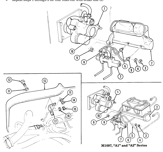
Disconnect brake lines (5) and (6) from master cylinder (2). 2. Remove locknut (3), washer (4), and proportioning valve bracket (8) from right master cylinder mounting stud (10). Discard locknut (3).
-
Remove locknut (14), washer (11), capscrew (12), and washer (11) from bracket (17) and splash shield (13).
-
Remove locknut (15), washer (16), and bracket (17) from hydro-boost (1). Discard locknut (15).
Do not lean on master cylinder.
- Remove two locknuts (9) and master cylinder (2) from hydro-boost (1). Discard locknuts (9).
b. Installation
Ensure O-ring is properly seated on master cylinder prior to installation. Damage to master cylinder may result if O-ring is not properly seated.
-
Install master cylinder (2) on hydro-boost (1) with two locknuts (9). Tighten locknuts (9) to 22 lb-ft (30 N•m).
-
Install bracket (17) on hydro-boost (1) with washer (16) and locknut (15). Tighten locknut (15) to 22 lb-ft (30 N•m).
-
Install bracket (17) on splash shield (13) with washer (11), capscrew (12), washer (11), and locknut (14). Tighten locknut (14) to 26 lb-ft (35 N•m).
-
Install proportioning valve bracket (8) on stud (10) with washer (4) and locknut (3). Tighten locknut (3) to 22 lb-ft (30 N•m).
-
Connect brake lines (5) and (6) to master cylinder (2).
7-13. Master Cylinder Maintenance (Cont'D)
c. Bleeding
Master cylinder must be filled (para. 2-11, pg 2-12, Item 11) and kept at least half full during bleeding operation.
Depress brake pedal slowly and hold. Loosen brake line (5) to purge air from the front reservoir, 1.
Tighten brake line (5) and release brake pedal.
Repeat steps 1 and 2 until front reservoir is purged of air.
Repeat steps 1 through 3 for rear reservoir with brake line (6)
FOLLOW-ON TASK: Bleed brake system (para. 7-10).
7-14. Hydro-Boost Replacement
This task covers: INITIAL SETUP:
Tools
General mechanic's tool kit: automotive (Appendix B, Item 1) Materials/Parts Cotter pin (Appendix G, Item 15) Spring tension washer (Appendix G, Item 317) Four lockwashers (Appendix G, Item 146) (Basic/A1 Series) Four lockwashers (Appendix G, Item 133) (A2 Series) a. Removal
a. Removal b. Installation
Personnel Required One mechanic One assistant Manual References TM 9-2320-280-24P Equipment Condition Master cylinder removed (para. 7-13).
Cover or plug all open lines and connections immediately after disconnection to prevent contamination. Remove all plugs prior to connection.
Have drainage container ready to catch brake fluid.
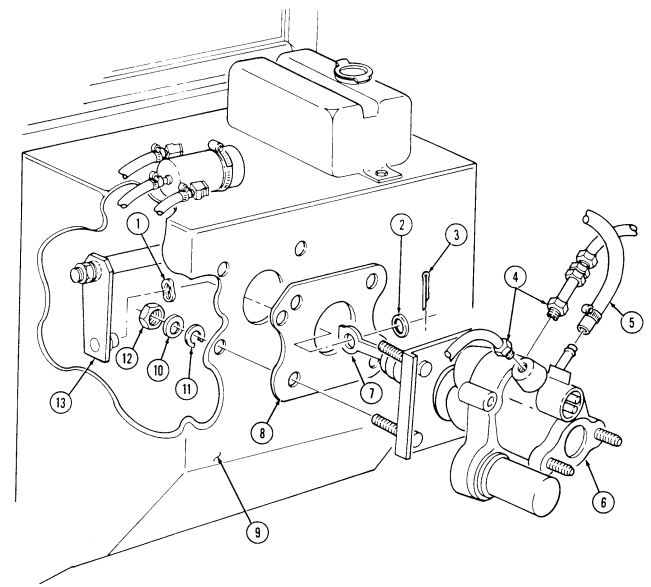
- Mark and disconnect two high pressure lines (4) and one return line (5) from hydro-boost (6). 2. Remove cotter pin (3), washer (2), and disconnect pushrod (7) from brake pedal bellcrank (13).
Remove spring tension washer (1) from brake pedal bellcrank (13) and discard cotter pin (3) and spring tension washer (1).
- Remove four nuts (12), lockwashers (11), washers (10), hydro-boost (6), and gasket (8) from cowl (9).
Discard lockwashers (11).
B. Installation
-
Install gasket (8) and hydro-boost (6) on cowl (9) with four washers (10), lockwashers (11), and nuts (12).
-
Install spring tension washer (1) on brake pedal bellcrank (13). Connect hydro-boost pushrod (7) to brake pedal bellcrank (13). Install washer (2) and cotter pin (3).
-
Tighten nuts (12) to 21 lb-ft (28 N•m). 4. Connect two high pressure lines (4) and one return line (5) to hydro-boost (6).
FOLLOW-ON TASKS: - Install master cylinder (para. 7-13).
- Bleed power steering system (para. 8-29).
7-15. Brake Lines Replacement
This task covers: c. Rear Brake Line Removal Removal e. Intermediate Brake Line Removal Installation g. Proportioning Valve to Union Brake Line l. Caliper to Tee Support Brackets Installation Removal a. Caliper to Tee Brake Line Removal h. Proportioning Valve to Union Brake Line Installation b. Caliper to Tee Brake Line Installation i. Proportioning Valve to Front Tee Brake Line d. Rear Brake Line Installation j. Proportioning Valve to Front Tee Brake Line f. Intermediate Brake Line Installation k. Caliper to Tee Support Brackets Removal
Initial Setup:
Tools General mechanic's tool kit: automotive (Appendix B, Item 1)
Materials/Parts
Four tiedown straps (Appendix G, Item 310) Locknut (Appendix G, Item 81) Manual References TM 9-2320-280-10 TM 9-2320-280-24P Equipment Condition
- Hood raised and secured (TM 9-2320-280-10). - Brake protection guards removed (para. 7-8.1).
Cover or plug all open lines and connections immediately after disconnection to prevent contamination. Remove all plugs prior to connection.
- Have drainage container ready to catch brake fluid. - Brake line replacement procedures for the service brake system and the rear dual service/parking brake system are basically the same. (Service brake system shown).
A. Caliper To Tee Brake Line Removal Note
-
Removal procedures are basically the same for all caliper to tee brake lines except M1123 and "A2" vehicles.
-
Brake lines on M1123 and "A2" series vehicles are not disconnected at tee line.
-
Steps 1 through 3 cover the right rear caliper to tee line (M998/A1).
-
Perform steps 4 through 9 for the left front caliper to tee line (M998A2).
-
Perform steps 10 through 14 for the left rear caliper to tee line (M998A2).
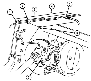
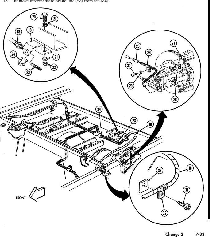
- Disconnect brake line (1) from caliper (7). 2. Disconnect brake line (1) from rear tee (5) at forward rear crossmember (4). 3. Remove capscrew (6) and clamp (2) securing brake line (1) and vent line (3) to forward rear crossmember (4) and remove brake line (1) from clamp (2).
7-15. Brake Lines Replacement (Cont'D)
7-15. Brake Lines Replacement (Cont'D)
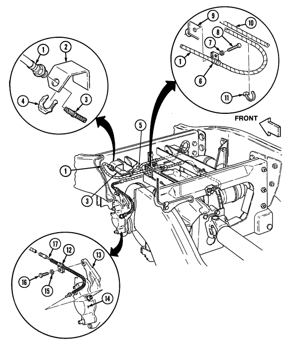
Disconnect left front brake line (17) from caliper (14).
Remove capscrew (16), washer (15), and clamp (12) from yoke (13).
Remove capscrew (8), washer (7), and clamp (6) from bracket (9).
Remove two tiedown straps (11) from brake lines (1) and (10). Discard tiedown straps (11).
Remove clip (4) and left front brake line (1) from bracket (2) and intermediate brake line (3). Remove intermediate brake line (3) from tee (5).
7 - 1 5 . Brake Lines Replacement (Cont'D)
-
Disconnect left rear brake line (25) from caliper (28).
-
Remove capscrew (30), washer (29), and clamp (26) from yoke (27).
-
Remove capscrew (31), clamp (32), and left rear brake line (18) from bracket (33). 13. Remove clip (24) and left rear brake line (18) from bracket (19) and intermediate brake line (23). 14. Remove locknut (22), two washers (21), screw (20), and bracket (19). Discard locknut (22).
7 - 1 5 . Brake Lines Replacement (Cont'D)
b. Caliper to Tee Brake Line Installation
Note
-
Installation procedures are basically the same for all caliper to tee brake lines except M1123 and "A2" vehicles.
-
Steps 1 through 4 covers the right rear caliper to tee line (basic and A1).
-
Perform steps 5 through 9 for the left front caliper to tee line (M1123 and "A2").
-
Perform steps 10 through 15 for the left rear caliper to tee line (M1123 and "A2").
1 . Connect brake line (1) to rear tee (5) at forward rear crossmember (4). 2 . Connect brake line (1) to caliper (7). 3 . Install brake line (1) and vent line (3) in clamp (2).
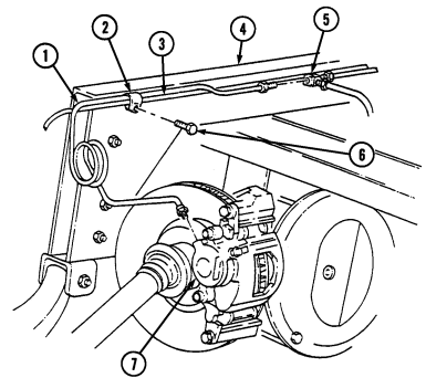 4 . Install brake line (1), vent line (3), and clamp (2) to forward rear crossmember (4) with capscrew ( 6 ) .
7-15. Brake Lines Replacement (Cont'D)
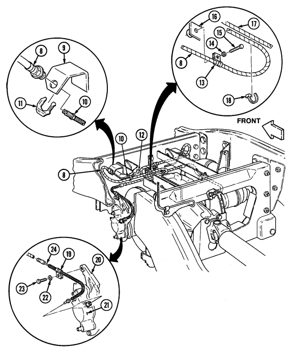
Install left front brake line (8) on intermediate brake line (10) and bracket (9) with clip (11). Connect left front brake line (24) to caliper (21) 7.
Install clamp (13) and left front brake line (8) on bracket (16) with washer (14) and capscrew (15). Secure brake lines (8) and (17) with two tiedown straps (18).
Install clamp (19) and brake line (24) on yoke (20) with washer (22) and capscrew (23).
Install intermediate brake line (10) to tee (12).
7 - 1 5 . Brake Lines Replacement (Cont'D)
- Install clamp (16) and brake line (1) on bracket (17) with capscrew (15). 14. Install clamp (10) and brake line (9) on yoke (11) with washer (13) and capscrew (14).
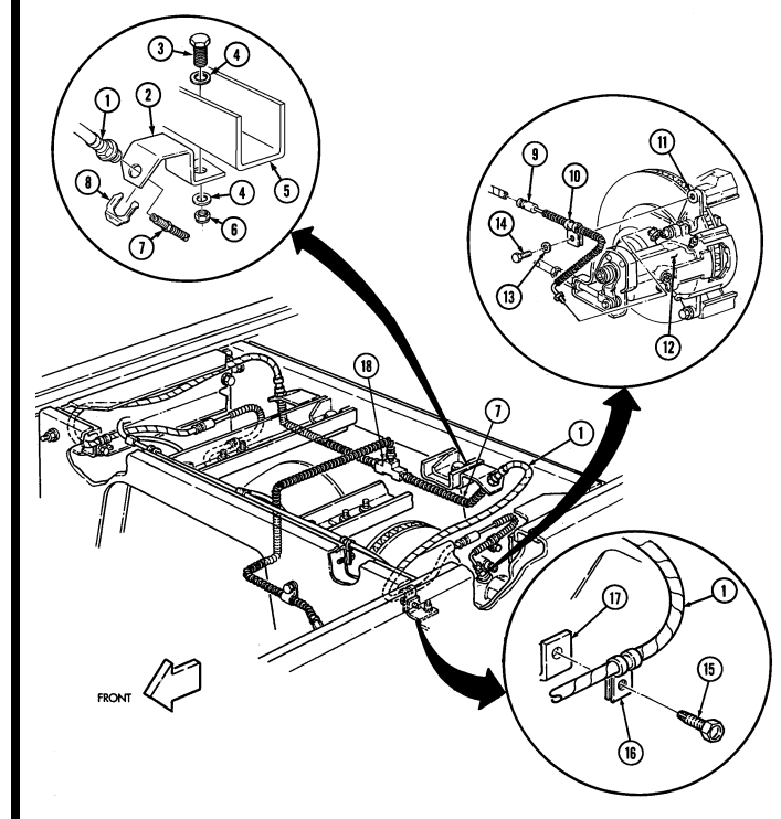 15. Connect intermediate brake line (7) to tee (18).
-
Install bracket (2) to crossmember (5) with washer (4), screw (3), washer (4), and locknut (6).
-
Install left rear brake line (1) on intermediate brake line (7) and bracket (2) with clip (8).
-
Connect left rear brake line (9) to caliper (12).
7 - 1 5 . Brake Lines Replacement (Cont'D)
c. Rear Brake Line Removal 1 . Disconnect rear brake line (20) from rear tee (19). 2 . Remove capscrew (23) and clamp (22) from rear brake line (20) and forward rear crossmember (21). 3 . Remove rear brake line (20) from intermediate brake line (24).
d. Rear Brake Line Installation 1 . Install rear brake line (20) to intermediate brake line (24). 2 . Install rear brake line (20) and clamp (22) to forward rear crossmember (21) with capscrew (23).
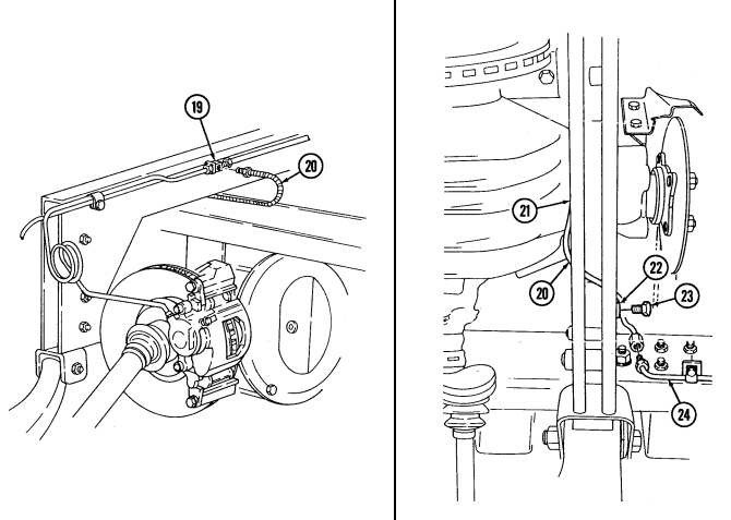 3 . Connect rear brake line (20) to rear tee (19).
7 - 1 5 . Brake Lines Replacement (Cont'D)
e. Intermediate Brake Line Removal 1 . Disconnect intermediate brake line (4) from rear brake line (1). 2 . Remove five capscrews (3) and clamps (2) securing intermediate brake line (4) to frame (5). 3 . Remove intermediate brake line (4) from proportioning valve to union brake line (6).
F. Intermediate Brake Line Installation
- Install intermediate brake line (4) to proportioning valve to union brake line (6). 2. Connect intermediate brake line (4) to rear brake line (1). 3. Install intermediate brake line (4) and five clamps (2) to frame (5) with five capscrews (3).
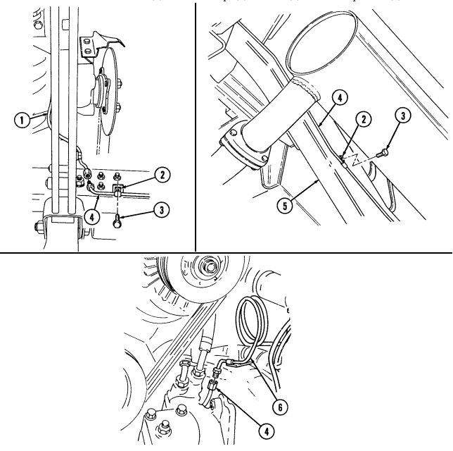
7 - 1 5 . Brake Lines Replacement (Cont'D)
g. Proportioning Valve to Union Brake Line Removal 1. Disconnect brake line (7) from proportioning valve (11). 2. Remove nut (14), washer (13), capscrew (9), and clamp (8) from brake line (7) and bracket (15). 3. Remove brake line (7) from union (16).
h. Proportioning Valve to Union Brake Line Installation 1. Connect brake line (7) to union (16). 2. Install brake line (7) and clamp (8) to bracket (15) with capscrew (9), washer (13), and nut (14). 3. Connect brake line (7) to proportioning valve (11).
i. Proportioning Valve to Front Tee Brake Line Removal
- Disconnect brake line (10) from proportioning valve (11). 2. Remove brake line (10) from front tee (12).
j. Proportioning Valve to Front Tee Brake Line Installation
- Connect brake line (10) to front tee (12).
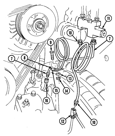 2. Connect brake line (10) to proportioning valve (11).
7 - 1 5 . Brake Lines Replacement (Cont'D)
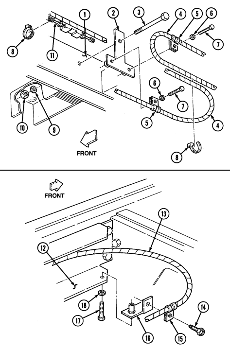
k. Caliper to Tee Support Brackets Removal
Note
- Perform steps 1 through 3 for front support bracket. - Perform steps 4 through 6 for rear support bracket.
-
Remove two tiedown straps (8) from front brake lines (4) and intermediate brake line (11). Discard tiedown straps (8).
-
Remove two capscrews (7), washers (6), and clamps (5) from bracket (2). 3. Remove nut (10), washer (9), capscrew (3), and support bracket (2) from crossmember (1). 4. Remove capscrew (14), clamp (15), and brake line (13) from left support bracket (16). 5. Remove capscrew (17), washer (18), and left support bracket (16) from frame bracket (12). 6. Repeat steps 4 and 5 for right support bracket.
L. Caliper To Tee Support Brackets Installation Note
- Perform steps 1 through 3 for front support bracket. - Perform steps 4 through 6 for rear support bracket.
- Install support bracket (2) on crossmember (1) with capscrew (3), washer (9), and nut (10). 2. Install two clamps (5) on support bracket (2) with two washers (6) and capscrews (7). 3. Secure front brake lines (4) and intermediate brake line (11) with two tiedown straps (8). 4. Install left support bracket (16) on frame bracket (12) with washer (18) and capscrew (17). 5. Install brake line (13) and clamp (15) on support bracket (16) with capscrew (14). 6. Repeat steps 4 and 5 for right support bracket.
7-15. Brake Lines Replacement (Cont'D)
FOLLOW-ON TASK: Install brake protection guards (para. 7-8.1).
7-16. Service Brake Pedal (12338394) Replacement
This task covers:
| Removal | a. | b. Installation |
|---|---|---|
| INITIAL SETUP: | ||
| Applicable Models | Manual References | |
| All M1123 and "A2" series vehicles | TM 9-2320-280-24P | |
| Tools | Equipment Condition | |
| General mechanic's tool kit: | Vehicle raised and supported (para. 8-2). | |
| automotive (Appendix B, Item 1) | ||
| Materials/Parts | ||
| Six locknuts (without 10,500 lb hydraulic | ||
| winch) (Appendix G, Item 128) | ||
| Three locknuts (with 10,500 lb hydraulic | ||
| winch) (Appendix G, Item 128) | ||
| Six locknuts (Appendix G, Item 79) |
A. Removal
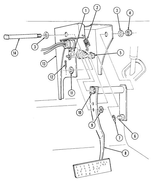
- Remove push on nut (9) and disconnect stoplight switch rod (1) from brake pedal assembly (8).
Discard push on nut (9).
B. Installation
- Disconnect return spring (2) from brake pedal assembly (8). 3. Remove cotter pin (12), washer (11), and hydro-boost pushrod (5) from brake pedal bellcrank (6).
Remove spring tension washer (7). Discard cotter pin (12) and spring tension washer (7).
-
Remove nut (4), two washers (3), pivot pin (14), and brake pedal assembly (8) from bracket (13). 5. Remove two sleeve bearings (10) from brake pedal assembly (8). Discard sleeve bearings (10).
-
Apply grease to inside of two sleeve bearings (10). Install two sleeve bearings (10) in brake pedal assembly (8).
-
Install brake pedal assembly (8) to bracket (13) with pivot pin (14), two washers (3), and nut (4).
Using adapter and crowfoot, tighten nut (4) to 60 lb-ft (81 N•m).
-
Install spring tension washer (7) to brake pedal bellcrank (6). Connect hydro-boost pushrod (5) to brake pedal bellcrank (6) with washer (11) and cotter pin (12).
-
Connect return spring (2) to brake pedal assembly (8). 5. Connect stoplight switch rod (1) to brake pedal assembly (8) with push on nut (9).
7-16. Service Brake Pedal (12338394) Replacement (Cont'D)
FOLLOW-ON TASKS: - Install protective control box (para. 4-5).
- Operate vehicle (TM 9-2320-280-10) and check brakes for proper operation.
7-17. Service Brake Pedal (Ex 5935037) Replacement
This task covers:
| TASK | PAGE |
|---|---|
| PARA. | PROCEDURES |
| 7-10. | Service Brake System Bleeding Instructions |
| 7-11. | Service Brake Pad Maintenance |
| 7-12. | Service Brake Caliper Maintenance |
| 7-13. | Master Cylinder Maintenance |
| 7-14. | Hydro-Boost Replacement |
| 7-15 | Brake Lines Replacement |
| 7-16. | Service Brake Pedal (12338394) Replacement |
| 7-17. | Service Brake Pedal (EX 5935037) Replacement |
| 7-18. | Proportioning Valve Replacement |
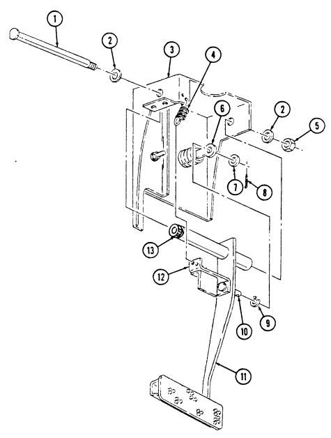
a. Removal 1. Disconnect return spring (4) from brake pedal bracket (12). 2. Remove cotter pin (8) and washer (7) securing hydro-boost pushrod (6) to brake pedal bellcrank (10), and disconnect hydro-boost pushrod (6) from brake pedal bellcrank (10). Remove spring tension washer (9) from bellcrank (10). Discard cotter pin (8) and spring tension washer (9).
-
Remove nut (5), washer (2), pivot pin (1), and washer (2) securing brake pedal assembly (11) to bracket (3) and remove brake pedal assembly (11).
-
Remove two sleeve bearings (13) from brake pedal assembly (11). Discard sleeve bearings (13).
B. Installation
-
Apply grease to inside of two sleeve bearings (13). Install two sleeve bearings (13) in brake pedal assembly (11).
-
Install brake pedal assembly (11) on bracket (3) with washer (2), pivot pin (1), washer (2), and nut (5). Using adapter and crowfoot, tighten nut (5) to 60 lb-ft (81 N•m).
-
Install spring tension washer (9) on brake pedal bellcrank (10). Connect hydro-boost pushrod (6) to brake pedal bellcrank (10) with washer (7) and cotter pin (8).
-
Connect return spring (4) to brake pedal bracket (12).
7-17. Service Brake Pedal (Ex 5935037) Replacement (Cont'D)
FOLLOW-ON TASKS: - Install stoplight switch (para. 4-61).
· Install protective control box (para. 4-5).
- Operate vehicle (TM 9-2320-280-10) and check brakes for proper operation.
7-18. Proportioning Valve Replacement
This task covers: INITIAL SETUP:
Tools
General mechanic's tool kit: automotive (Appendix B, Item 1)
a. Removal b. Installation
| Manual References |
|---|
| TM 9-2320-280-10 |
| Equipment Condition |
|---|
Materials/Parts Locknut (Appendix G, Item 128) Lubricating oil (Appendix C, Item 33)
- Battery ground cable disconnected (para. 4-73). - Hood raised and secured (TM 9-2320-280-10).
A. Removal Caution
-
Prior to removal, tag brake lines for installation. - Cover or plug all open lines and connections immediately after disconnection to prevent contamination. Remove all plugs prior to connection.
-
Do not attempt to disassemble proportioning valve. Damage to equipment will result.
Have drainage container ready to catch brake fluid.
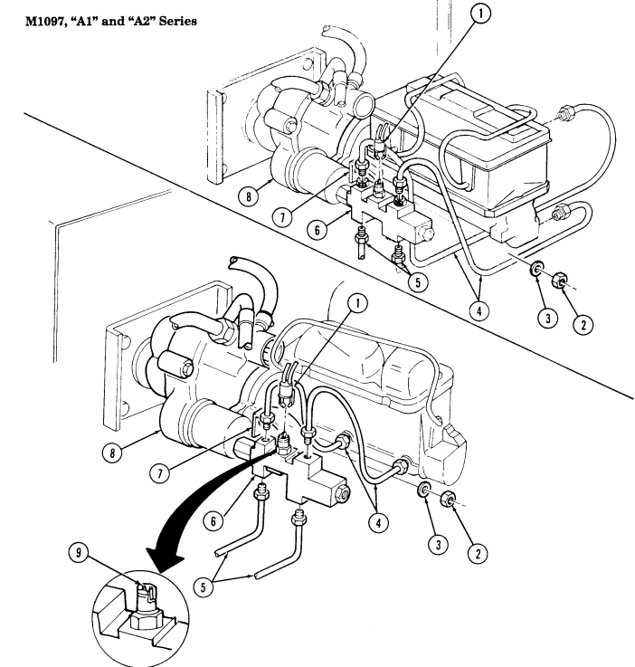
- Disconnect electrical connector (1) from proportioning valve (6). 2. Disconnect two brake lines (5) from proportioning valve (6). 3. Disconnect two brake lines (4) from proportioning valve (6). 4. Remove locknut (2), washer (3), and proportioning valve (6) from hydro-boost (8) and proportioning valve bracket (7). Discard locknut (2).
B. Installation
-
Install proportioning valve (6) to proportioning valve bracket (7) and hydro-boost (8) with washer (3) and locknut (2). Tighten locknut (2) to 22 lb-ft (30 N•m).
-
Connect two brake lines (5) to proportioning valve (6). 3. Connect two brake lines (4) to proportioning valve (6). 4. Apply lubricating oil to pins (9) of proportioning valve (6). 5. Connect electrical connector (1) to proportioning valve (6).
7-18. Proportioning Valve Replacement (Cont'D)
FOLLOW-ON TASKS: - Connect battery ground cable (para. 4-73).
- Bleed brake system (para. 7-10).
7-19. Service Brake Rotor Replacement
This task covers: INITIAL SETUP:
Tools
General mechanic's tool kit: automotive (Appendix B, Item 1) Materials/Parts Six lockwashers (Appendix G, Item 145) Sealing compound (Appendix C, Item 43) a. Removal b. Installation Manual References TM 9-2320-280-24P Equipment Condition Service brake pad removed (para. 7-11).
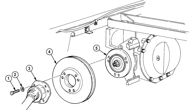
a. Removal 1. Remove six capscrews (1) and lockwashers (2) from halfshaft (3), rotor (4), and output flange (5).
Discard lockwashers (2).
- Disconnect halfshaft (3) and remove rotor (4) from output flange (5).
b. Installation 1. Apply sealing compound to threads of capscrews (1). 2. Install rotor (4) on output flange (5). 3. Connect halfshaft (3) to rotor (4) and install six lockwashers (2) and capscrews (1). Tighten capscrews (1) to 48 lb-ft (65 N•m).
FOLLOW-ON TASK: Install service brake pad (para. 7-11).
Section Iii. Rear Dual Service/Parking Brake System Maintenance
7-20. REAR DUAL SERVICE/PARKING BRAKE SYSTEM MAINTENANCE TASK SUMMARY
| INITIAL SETUP: | |
|---|---|
| Tools | Personnel Required |
| General mechanic's tool kit: | One mechanic |
| automotive (Appendix B, Item 1) | One assistant |
| Materials/Parts | Manual References |
| Cotter pin (Appendix G, Item 15) | TM 9-2320-280-24P |
| Spring tension washer (Appendix G, Item 317) | |
| Four lockwashers (Appendix G, Item 146) | Equipment Condition |
| (Basic/A1 Series) | Master cylinder removed (para. 7-13). |
| Four lockwashers (Appendix G, Item 133) | |
| (A2 Series) | |
| a. Removal | |
| CAUTION |
7-21. Rear Dual Service/Parking Brake Pad Maintenance
This task covers: a. Removal c. Installation b. Cleaning and Inspection
Initial Setup:
Tools General mechanic's tool kit: automotive (Appendix B, Item 1) Hex wrench (Appendix D, Fig. D 115) Open end wrench (Appendix D, Fig. D 116) Special Tools Crowfoot, 14 mm (Appendix B, Item 152) Materials/Parts Retaining ring (Appendix G, Item 231) Cotter pin (Appendix G, Item 12) Sealing compound (Appendix C, Item 45) Grease (Appendix C, Item 22) Tiedown strap (Appendix G, Item 312) Manual References TM 9-2320-280-10 TM 9-2320-280-24P Equipment Condition
-
Wheels chocked and parking brake released (TM 9-2320-280-10).
-
Pioneer tool stowage rack removed (TM 9-2320-280-10).
General Safety Instructions Make sure brake pads are installed with linings facing rotor.
The following procedure applies to vehicles with serial numbers USBL, Eff, 44825 and above.
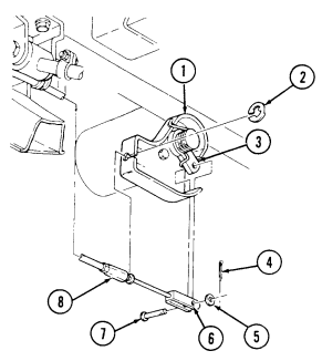
a. Removal 1.Remove cotter pin (4), washer (5), and clevis pin (7) from parking brake clevis (6) and lever (3).
Discard cotter pin (4).
2.Remove retaining ring (2) and disconnect parking brake cable (8) from caliper cable bracket (1).
Discard retaining ring (2)
Use tiedown strap to support caliper during removal to prevent damage to brake line.
3.Remove two capscrews (12), washers (13), and pull yoke (14) and caliper (15) away from rotor (10).
Note positioning of brake pad surfaces for installation.
4.Remove two brake pads (9) from adapter (11) and rotor (10).
7-21. REAR DUAL SERVICE/PARKING BRAKE PAD MAINTENANCE (Cont'd)
7 - 2 1 . Rear Dual Serv I C E / Parking Brake Pad Maintenance (Cont'D)
b. Cleaning and Inspection
Note
Apply a light coat of grease on adapter slides.
-
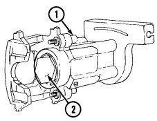
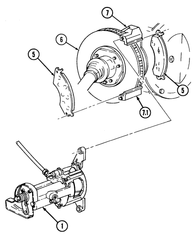
Clean mating surfaces of caliper (1) and adapter (7) and lubricate adapter slides (7.1) with grease. 2. Inspect caliper (1) and caliper piston face (3) for cracks, pitting, or damage. Replace caliper assembly if cracked, pitted, or damaged (para. 7-22).
-
Inspect dust boot (2) for tears or deterioration. Replace caliper assembly (1) if dust boot (2) is torn or deteriorated (para. 7-22).
-
Inspect caliper cable bracket (4) for looseness, damage, and rotation. If loose, damaged, or repositioned, replace caliper assembly (1).
-
Thoroughly clean and inspect rotor (6) for heat cracks, discoloration, pitting, or scoring. Replace rotor (6) if cracked, pitted, or scored (para. 7-19).
Ensure that grease and oil are not in contact with rotor and/or shoe and lining friction surface. Failure to do so will result in damage to equipment and poor performance.
Note
- Replace brake pads in axle sets only. - Replace brake pads if thickness is less than 3/16 in. (4.8 mm) and operation in wet and muddy conditions is expected.
- Inspect brake pads (5) for glazing, oil saturation, or wear. If glazed, oil saturated, or if brake pad thickness is less than 1/8 in. (3.2 mm), replace both pads (5) and pads on opposite caliper.
c. Installation
Ensure brake pads are installed with linings facing rotor. Failure to do this may cause injury to personnel or damage to equipment and poor performance.
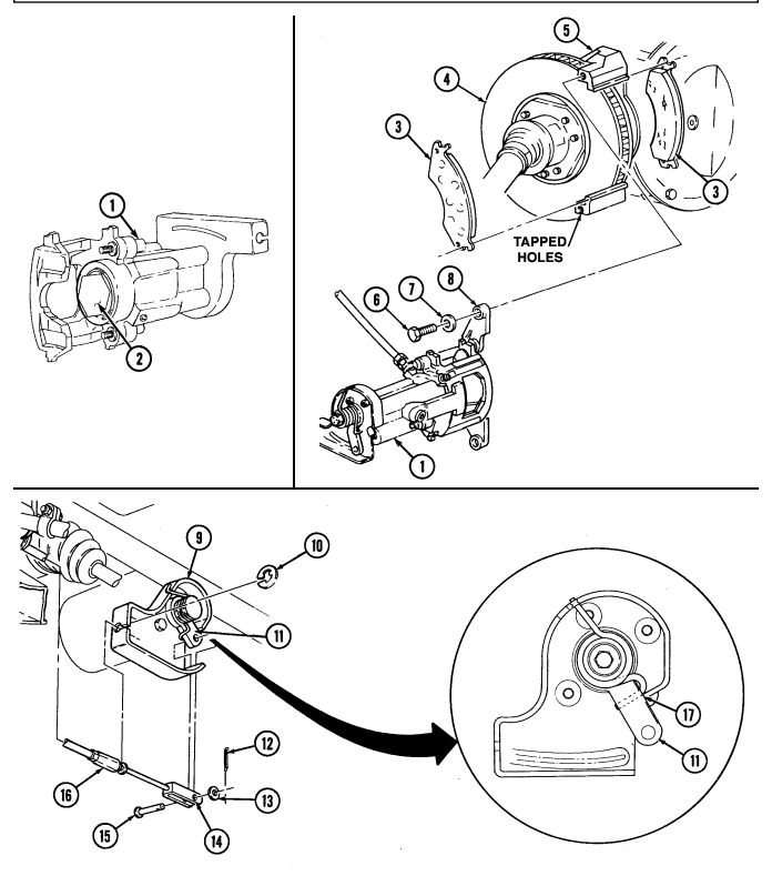
- Position brake pads (3) facing rotor (4) in adapter (5). 2. Apply sealing compound to tapped holes of adapter (5).
Applying force to piston cap will result in piston cap damage.
-
When installing yoke and caliper, use a "C" clamp and block of wood to bottom out piston in caliper if needed.
-
With caliper secured, use either hex wrench or open end wrench to rotate caliper piston in a clockwise direction and, at the same time, apply force on outer piston hex until caliper piston is seated in caliper bore.
-
Rotate caliper piston (2) in a clockwise direction and at the same time apply force on outer piston hex until caliper piston (2) is seated in piston bore.
-
Install caliper (1) and yoke (8) on adapter (5) and rotor (4) with two washers (7) and capscrews (6).
Using crowfoot, tighten capscrews (6) to 30-40 lb-ft (41-54 N•m).
- Install parking brake cable (16) on caliper cable bracket (9) with retaining ring (10).
-
Ensure lever is in contact with caliper cable bracket stop. Damage to equipment and poor performance will result if not aligned properly.
-
Ensure that the clevis and clevis pin are aligned to the lever. Do not move the lever to accommodate a misadjusted clevis. Damage to equipment and poor performance will result.
- Install parking brake clevis (14) on lever (11) with clevis pin (15), washer (13), and cotter pin (12).
Check position of lever (11) and make sure it is in contact with caliper cable bracket stop (17).
FOLLOW-ON TASKS: •Adjust rear dual service/parking brake (para. 7-26).
●Install pioneer tool stowage rack (TM 9-2320-280-10).
7-22. Rear Dual Service/Parking Brake Caliper Maintenance
This task covers: a. Removal c. Installation b. Cleaning and Inspection INITIAL SETUP: Tools General mechanic's tool kit: automotive (Appendix B, Item 1) Special Tools Crowfoot, 14 mm (Appendix B, Item 152) Hex head driver, 7 mm (Appendix B, Item 162) Materials/Parts Cotter pin (Appendix G, Item 12) Flat washer (Appendix G, Item 38) Retaining ring (Appendix G, Item 231) Sealing compound (Appendix C, Item 45)
Manual References
TM 9-2320-280-10 TM 9-2320-280-24P
Equipment Condition
-
Wheels chocked and parking brake released (TM 9-2320-280-10).
-
Pioneer tool stowage rack removed (TM 9-2320-280-10).
General Safety Instructions Make sure brake pads are installed with linings facing rotor.
a. Removal
Cover or plug all open lines and connections immediately after disconnection to prevent contamination. Remove all plugs prior to connection.
The following procedure applies to vehicles with serial numbers USBL, Eff, 44825 and above.
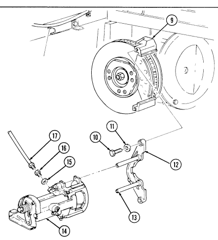
1.Remove cotter pin (4), washer (5), and clevis pin (7) from parking brake clevis (6) and lever (3).
Discard cotter pin (4).
2.Remove retaining ring (2) and disconnect parking brake cable (8) from caliper cable bracket (1).
Discard retaining ring (2).
Have drainage container ready to catch brake fluid.
3.Disconnect brake line (17) from coupling (16). 4.Remove coupling (16) and flat washer (15) from caliper (14). Discard flat washer (15).
Caliper must be supported during removal to prevent damage to brake line.
5.Remove two capscrews (10), washers (11), yoke (12), and caliper (14) from adapter (9). 6.Slide yoke (12) and location pins (13) out from caliper (14).
7-22. REAR DUAL SERVICE/PARKING BRAKE CALIPER MAINTENANCE (Cont'd)
b. Cleaning and Inspection
Apply a light coat of grease on adapter slides.
-
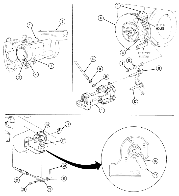
Clean mating surfaces of caliper (1) and adapter (7) and lubricate adapter slides with grease. 2. Clean cooling fins of rotor (6). 3. Inspect caliper (1) and caliper piston face (4) for cracks, pitting, or damage. Replace caliper assembly if cracked, pitted, or damaged.
-
Inspect caliper cable bracket (5) for looseness, damage, and rotation. If loose, damaged, or repositioned, replace caliper assembly (1).
-
Inspect dust boot (3) for tears or deterioration. Replace caliper assembly if dust boot (3) is torn or deteriorated.
-
Inspect rotor (6) for heat cracks, discoloration, pitting, or damage. Replace rotor (6) if cracked, pitted, or scored (para. 7-19).
-
Inspect yoke locating pins (12) for cracks or corrosion. Perform step 8 if cracked or corroded. If not, perform step 9.
-
Using 7 mm hex driver, remove locating pins (12) from yoke (11). Discard locating pins (12). 9. Inspect brake pads (8) for glazing, oil saturation, or wear. If glazed, oil saturated, or if brake pad thickness is less than 1/8 in. (3.2 mm), replace both pads (8) and pads on opposite caliper (para. 7-21).
Ensure that grease and oil are not in contact with rotor and/or brake shoe friction surfaces. Failure to do so will result in damage to equipment and poor performance.
C. Installation
- Open bleeder valve (2) and depress piston (4) into caliper (1) while rotating piston (4) in a clockwise direction, and at the same time apply pressure until piston (4) is seated in piston bore.
Perform step 2 only if yoke locating pins were removed.
-
Apply sealing compound to threads of locating pins (12) and install locating pins (12) in yoke (11) using 7 mm hex head driver. Tighten locating pins (12) to 25-35 lb-ft (34-47 N•m).
-
Slide yoke (11) and locating pins (12) into caliper (1). 4. Apply sealing compound to tapped holes of adapter (7). 5. Install caliper (1) and yoke (11) on adapter (7) with two washers (10) and capscrews (9). Using crowfoot, tighten capscrews (9) to 30-40 lb-ft (41-54 N•m).
-
Install flat washer (15) and coupling (14) on caliper (1) and connect brake line (13) to coupling (14).
-
Install parking brake cable (24) on caliper cable bracket (18) with retaining ring (19).
- Ensure lever is in contact with caliper cable bracket stop.
Damage to equipment and poor performance will result if not alined properly.
- Ensure that the clevis and clevis pin are alined to lever. Do not move the lever to accommodate a misadjusted clevis, or damage to equipment and poor performance will result.
- Check position of lever (17) and ensure it is in contact with caliper cable bracket stop (16). 9. Install parking brake clevis (22) to lever (17) with clevis pin (23), washer (21), and cotter pin (20).
FOLLOW-ON TASKS: - Install service brake rotor (para. 7-19).
- Bleed brake system (para. 7-10). · Adjust rear dual service/parking brake (para. 7-26). · Install pioneer tool stowage rack (TM 9-2320-280-10).
7-23. Right Parking Brake Cable Replacement
A. Removal B. Installation Note Note Note Note
| Materials/Parts |
|---|
| Materials/Parts |
|---|
This task covers: General mechanic's tool kit: automotive (Appendix B, Item 1) Cotter pins (Appendix G, Item 12) Two lockwashers (Appendix G, Item 163) Two retaining rings (Appendix G, Item 231) Two locknuts (Appendix G, Item 71) Lockwasher (Appendix G, Item 135)
-
Muffler and insulator removed (all models except M1123 and "A2" vehicles) (para. 3-48).
-
Muffler and catalytic converter removed (M1123 and "A2" vehicles only) (para. 3-49).
-
Wheels chocked and parking brake released (TM 9-2320-280-10).
-
The following procedure applies to vehicles with serial numbers USBL Eff. 44825 and above.
-
If cables are chafing or crushed, use new cable clamp bracket.
-
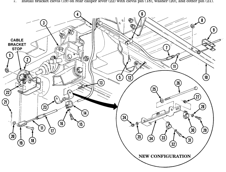
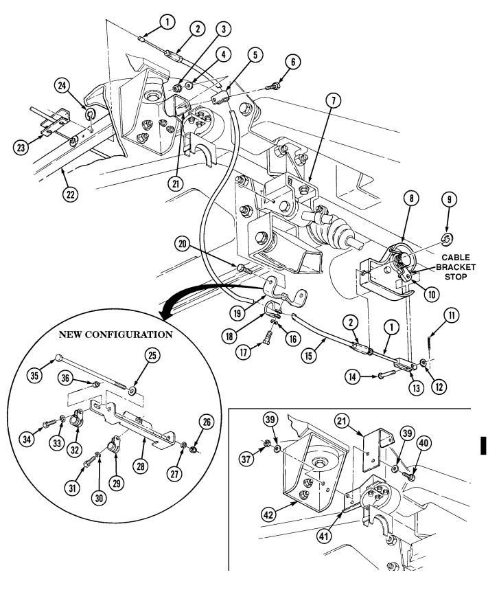
Remove cotter pin (21), washer (20), clevis pin (18), and brake clevis (19) from rear caliper lever (22). Discard cotter pin (21).
-
Remove brake cable retaining ring (1) and parking brake cable sleeve (17) from rear caliper cable bracket (2) and remove cable assembly (4) from caliper cable bracket (2). Discard cable retaining ring (1).
-
Slide parking brake cable (11) through parking brake cable assembly (4). Remove parking brake cable retaining ring (8) from parking brake cable sleeve (7) and "C" beam (10). Disconnect parking brake cable (4) from parking brake equalizer bar (9). Discard cable retaining ring (8).
-
Remove two capscrews (5), parking brake cable clamps (6), and parking brake cable assembly (4) from body (12).
Perform steps 5 and 6 for vehicles with old parking brake cable bracket. Perform steps 7 through 9 for vehicles with new parking brake cable bracket configuration.
- Remove capscrew (15), lockwasher (16), and parking brake cable clamp (14) from bracket (23).
Discard lockwasher (16).
-
Remove two capscrews (13) and clamp bracket (23) from support bracket (3). Discard clamp bracket (23). 7. Remove locknut (27), capscrew (29), lockwasher (28), and parking brake cable clamp (30) from clamp bracket (34). Discard locknut (27) and lockwasher (28).
-
Remove capscrew (31), lockwasher (32), and parking brake cable clamp (33) from bracket (34).
Discard lockwasher (32).
Perform step 9 if clamp bracket is damaged. If not replacing bracket proceed to b., installation.
bracket (3). Discard locknut (24).
-
Remove locknut (24), washer (35), capscrew (26), washer (25), and clamp bracket (34) from support b. Installation Ensure clamp bracket (P/N 12342965) is installed on vehicle.
-
Install clamp bracket (34) on support bracket (3) with washer (25), capscrew (26), washer (35), and locknut (24).
7-56 Change 3 INITIAL SETUP: Tools a. Removal
-
Slide parking brake cable clamp (33) onto parking brake cable assembly (4) and install on clamp bracket (34) with lockwasher (32) and capscrew (31).
-
Slide parking brake cable clamp (30) on parking brake cable assembly (4) and install on clamp bracket (34) with capscrew (29), lockwasher (28), and locknut (27).
-
Install two parking brake cable clamps (6) on parking brake cable assembly (4) and install parking brake cable clamps (6) on underbody (12) with two capscrews (5).
-
Install parking brake cable sleeve (7) to "C" beam (10) and parking brake cable (11) to equalizer bar (9) with retaining ring (8).
Ensure that the caliper cable bracket is secure with no signs of looseness and the lever is in contact with the caliper cable bracket stop. Damage to equipment and poor performance will result if not aligned properly.
- Install parking brake cable sleeve (17) to caliper cable bracket (2) with cable retaining ring (1).
FOLLOW-ON TASKS: - Adjust parking brake lever (TM 9-2320-280-10).
- Install muffler and catalytic converter (M1123 and "A2" vehicles only) (para. 3-49). - Install muffler and insulator (all models except M1123 and "A2" vehicles) (para. 3-48).
7-24. Left Parking Brake Cable/Mounting Bracket Replacement
This task covers: INITIAL SETUP: Tools General mechanic's tool kit: automotive (Appendix B, Item 1) Materials/Parts Assembled locknut (Appendix G, Item 130) Two lockwashers (Appendix G, Item 135) Cotter pin (Appendix G, Item 12) Two retaining rings (Appendix G, Item 231) Two locknuts (Appendix G, Item 71)
A. Removal B. Installation
Manual References TM 9-2320-280-10 TM 9-2320-280-24P Equipment Condition
-
Muffler and insulator removed (all models except M1123 and "A2" vehicles) (para. 3-48).
-
Muffler and catalytic converter removed (M1123 and "A2" vehicles only) (para. 3-49).
-
Wheels chocked and parking brake released (TM 9-2320-280-10).
-
The following procedure applies to vehicles with serial numbers USBL Eff. 44825 and above.
-
If cables are chafing or crushed, use new cable clamp bracket.
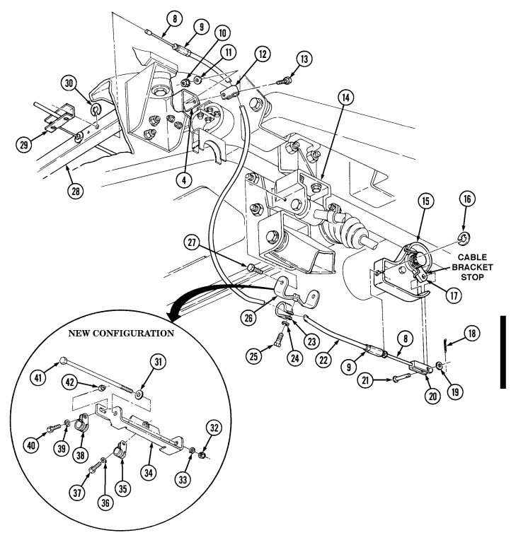
a. Removal 1. Remove cotter pin (11), washer (12), clevis pin (14), and brake clevis (13) from rear caliper lever (10).
Discard cotter pin (11).
-
Remove brake cable retaining ring (9) and parking brake cable sleeve (2) from rear caliper cable bracket (8). Discard cable retaining ring (9).
-
Slide parking brake cable (1) through parking brake cable assembly (15). Remove parking brake cable retaining ring (24) and parking brake cable sleeve (2) from "C" beam (22). Disconnect parking brake cable (1) from parking brake equalizer bar (23). Discard cable retaining ring (24).
-
Remove capscrew (6), washer (4), and assembled locknut (3) from brake cable clamp (5), mounting bracket (21) and parking brake cable assembly (15). Discard assembled locknut (3).
Perform steps 5 and 6 for vehicles with old parking brake cable bracket. Perform steps 7 through 9 for vehicles with new parking brake cable bracket configuration.
-
Remove capscrew (17), lockwasher (16), parking brake cable clamp (18), and parking brake cable assembly (15) from bracket (19). Discard lockwasher (16).
-
Remove two capscrews (20) and bracket (19) from support bracket (7). Discard bracket (19). 7. Remove locknut (36), capscrew (34), washer (33), and parking brake cable clamp (32) from bracket (28). Discard locknut (36).
-
Remove capscrew (31), lockwasher (30), and parking brake cable clamp (29) from bracket (28).
Discard lockwasher (30).
Perform step 9 if clamp bracket is damaged. If not replacing bracket, proceed to b., installation.
- Remove locknut (26), washer (27), capscrew (35), washer (25), and clamp bracket (28) from support bracket (7). Discard locknut (26).
Perform step 10 if replacing parking cable mounting bracket. If not replacing bracket, proceed to b., installation.
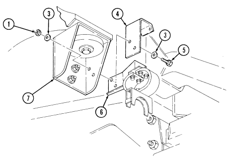
- Remove two nuts (37), washers (39), capscrews (40), washers (39), mounting bracket (21), and tailpipe hanger (41) from rear body mount (42).
NOTE
b. Installation
Perform step 1 if replacing parking brake cable mounting bracket. If not, proceed to step 2.
- Install parking brake cable mounting bracket (4) and tailpipe hanger (6) on rear body mount (7) with two capscrews (5), four washers (3), and two nuts (1).
Ensure clamp bracket (P/N 12342966) is installed on vehicle.
-
Install clamp bracket (34) on support bracket (14) with washer (31), capscrew (41), washer (33), and locknut (32).
-
Slide parking brake cable clamp (35) onto parking bracket cable assembly (22) and install cable clamp (35) on clamp bracket (34) with lockwasher (36) and capscrew (37).
-
Slide parking brake cable clamp (38) onto parking brake cable assembly (22) and install cable clamp (38) on clamp bracket (34) with capscrew (40), washer (39), and locknut (42).
-
Install parking brake cable clamp (12) on parking brake cable assembly (22) and install cable clamp (12) on parking brake cable mounting bracket (4) with washer (11), capscrew (13), and assembled locknut (10).
-
Install parking brake cable sleeve (9) on "C" beam (28) and parking brake cable (8) on equalizer bar (29) with retaining ring (30).
Ensure that the caliper cable bracket is secure with no signs of looseness and the lever is in contact with the caliper cable bracket stop. Damage to equipment and poor performance will result if not aligned properly.
- Install parking brake cable sleeve (9) on rear caliper cable bracket (15) with cable retaining ring (16).
 8. Install brake clevis (20) on rear caliper lever (17) with clevis pin (21), washer (19), and cotter pin (18). 9. Install parking brake cable assembly (22) on bracket (26) with clamp (23), capscrew (25), and lockwasher (24).
- Install bracket (26) on bracket (14) with two capscrews (27).
FOLLOW-ON TASKS: - Adjust parking brake lever (TM 9-2320-280-10).
- Install muffler and catalytic converter (M1123 and "A2" vehicles only) (para. 3-49). - Install muffler and insulator (all models except M1123 and "A2" vehicles) (para. 3-48).
Change 3
7-25. Rear Dual Service/Parking Brake Rod Replacement
This task covers: INITIAL SETUP:
Tools
General mechanic's tool kit: automotive (Appendix B, Item 1) Materials/Parts Three cotter pins (Appendix G, Item 12) Locknut (Appendix G, Item 79) Locknut (Appendix G, Item 86) Manual References TM 9-2320-280-10 TM 9-2320-280-24P
a. Removal b. Installation
Equipment Condition
-
Muffler and insulator removed (all models except M1123 and "A2" vehicles) (para. 3-48).
-
Muffler and catalytic converter removed (M1123 and "A2" vehicles only) (para. 3-49).
-
Wheels chocked and parking brake released (TM 9-2320-280-10).
The following procedure applies to vehicles with serial numbers USBLEff. 44825 and above.
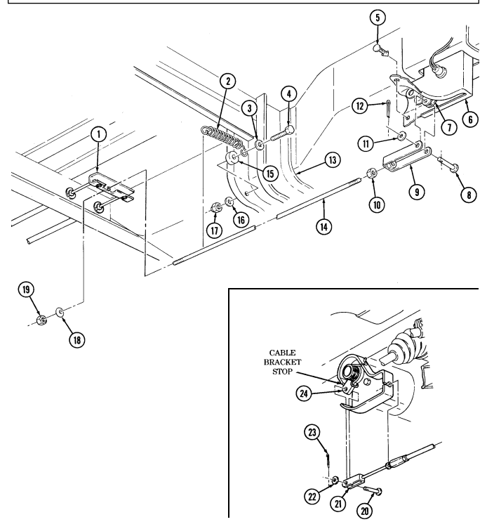
a. Removal 1. Remove two cotter pins (left and right) (23), washers (22), clevis pins (20), and brake clevis (21) from caliper levers (24). Discard cotter pins (23).
- Remove clip (5) and spread boot (6) to allow access to cotter pin (12).
B. Installation
-
Install spring (2) and spacer (15) on body (13) with washer (3), capscrew (4), washer (16), and locknut (17).
-
Install nut (10) and clevis (9) on brake rod (14). 3. Slide brake rod (14) rearward through spring (2). 4. Install brake rod (14) on brake cable equalizer bar (1) with conical washer (18) and locknut (19).
Tighten locknut (19) far enough to expose 3-5 threads on the end of brake rod (14).
- Spread boot (6) and install clevis (9) on bellcrank (7) with clevis pin (8), washer (11), and cotter pin (12). 6. Install clip (5) on boot (6).
Ensure that the caliper cable bracket is secure with no signs of looseness and the lever is in contact with the caliper cable bracket stop. Damage to equipment and poor performance will result if not aligned properly.
-
Install brake clevis (21) on rear caliper levers (24) with clevis pins (20), washers (22), and cotter pins (23).
-
Remove cotter pin (12), washer (11), clevis pin (8), and clevis (9) from brake rod (14) and bellcrank (7). Discard cotter pin (12).
-
Remove locknut (17), washer (16), spacer (15), washer (3), capscrew (4), and spring (2) from body (13). Discard locknut (17).
-
Remove locknut (19) and conical washer (18) from brake rod (14) and brake cable equalizer bar (1).
Discard locknut (19).
- Remove brake rod (14) by sliding brake rod (14) forward. 7. Remove clevis (9) and nut (10) from brake rod (14).
7-25. Rear Dual Service/Parking Brake Rod Replacement (Cont'D)
FOLLOW-ON TASKS: - Adjust rear dual service/parking brake (para. 7-26).
-
Install muffler and catalytic converter (M1123 and "A2" vehicles only) (para. 3-49).
-
Install muffler and insulator (all models except M1123 and "A2" vehicles) (para. 3-48).
7-26. Rear Dual Service/Parking Brake Adjustment
This task covers: Adjustment INITIAL SETUP: Tools General mechanic's tool kit: automotive (Appendix B, Item 1) Materials/Parts Cotter pin (Appendix G, Item 12) Personnel Required One mechanic One assistant Manual References TM 9-2320-280-10 TM 9-2320-280-24P Equipment Condition Wheels chocked and parking brake released (TM 9-2320-280-10).
-
The Kelsey-Hayes parking brake mechanism has an automatic adjusting feature and does not require periodic manual adjustment. When parking brake components or rear brake pads are replaced, the parking brake linkage must be initially positioned to ensure proper parking brake system operation. The only additional adjustment necessary is accomplished with the parking brake hand lever. Refer to TM 9-2320-280-10.
-
The following procedure applies to vehicles with serial numbers USBL Eff. 44825 and above.
Adjustment
-
Remove clip (1) and spread boot (2) to allow access to cotter pin (9). 2. Remove cotter pin (9), washer (8) and clevis pin (4) from clevis (5) and bellcrank (3). Discard cotter pin (9).
-
Repeatedly apply and adjust parking brake hand lever until bellcrank (3) linear travel is 0.75 in.
(19 mm).
Holes in parking brake clevis must aline to the holes in the adjusting bellcrank without force for proper parking brake adjustment. Failure to do this may result in damage to equipment and poor performance.
- Release parking brake. Loosen nut (6) and adjust clevis (5) so holes in clevis (5) align to holes in bellcrank (3). Install clevis (5) on bellcrank (3) with clevis pin (4), washer (8), and cotter pin (9).
Do not overtighten brake rod. Overtightening brake rod may result in dragging brakes.
- If necessary, remove excess slack in parking brake cables by turning the parking brake rod (7) clockwise or counterclockwise into the clevis (5).
Ensure that the caliper cable bracket is secure with no signs of looseness and the lever is in contact with the caliper cable bracket stop. Darnage to equipment and poor performance will result if not aligned properly.
Perform step 6 on both sides.
- Parking brake rod (7) is properly adjusted if lever (11) is in contact with caliper cable bracket
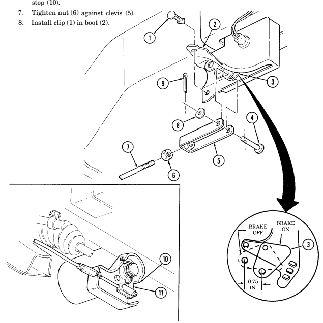
FOLLOW-ON TASK: Adjust parking brake lever (TM 9-2320-280-10).