hmmwv-manuals
Chapter 4 Electrical System Maintenance
Section I. GENERATING AND PROTECTIVE CONTROL BOX SYSTEM MAINTENANCE
| Chapter 4 | Systems Maintenance TASK SUMMARY |
|---|---|
| TASK | PROCEDURES |
| 4-2 | 60 Ampere Alternator Maintenance |
| 4-3 | Alternator Pulley Replacement |
| 4-4 | Alternator Mounting Brackets Replacement (Cont'D) |
| 4-5 | Protective Control Box Maintenance |
| 4-6 | Starter And Starting Control System Maintenance Task Summary |
| 4-7 | Rotary Switch Replacement |
| 4-8 | Starter Replacement |
| 4-9 | Circuit Breaker Replacement |
| 4-10 | INSTRUMENTS, SENDING UNITS, SWITCHES, AND HORN MAINTENANCE TASK |
| 4-11 | Instrument Cluster Replacement |
| 4-12 | Instrument Panel Replacement |
| 4-13 | Electrical Gauge Replacement |
| 4-14 | Speedometer/Odometer Replacement (Cont'D) |
| 4-15 | Speedometer Cable And Core (12338428) Replacement |
| 4-16 | Instrument Cluster Light Replacement |
| 4-17 | Wait-To-Start Lamp Replacement (Cont'D) |
| 4-18 | High Beam Lamp Replacement |
| 4-19 | Parking Brake Switch Replacement |
| 4-20 | Horn Switch Replacement |
| 4-21 | Horn Control Brush Replacement |
| 4-22 | Horn Replacement |
| 4-23 | Horn Mounting Bracket Replacement |
| 4-24 | Engine Temperature Sending Unit Replacement |
| 4-25 | Oil Pressure Sending Unit Replacement |
| 4-26 | Fuel Pressure Transducer Replacement |
| 4-27 | Cold Advance Switch Replacement |
| 4-28 | Fuel Level Sending Unit Replacement |
| 4-29 | Glow Plug Controller/Temperature Sensor Replacement |
| 4-30 | Fan Temperature Switch Replacement |
| 4-31 | Time Delay Module Replacement |
| 4-32 | Rpm Sensor Replacement |
| 4-33 | Engine Rpm Sensor Replacement |
| 4-34 | Backup Light Switch Replacement |
| 4-35 | |
| 4-36 | Transfer Case Indicator Switch Replacement |
| 4-37 | Transfer Case Indicator Lamp Cable Assembly Replacement |
| 4-38 | Transfer Case Indicator Lamp Assembly Replacement |
| 4-39 | Transmission Indicator Lamp Assembly Replacement (4L80-E) |
| 4-40 | Transmission Circuit Breakers And Jumper Leads Replacement (4L80-E) |
| 4-41 | Transmission Relay Replacement (4L80-E) |
| 4-42 | |
| 4-43 | Kick-Down Switch Maintenance (3L80) (Cont'D) |
| 4-44 | Fan Cut-Off Switch Replacement (4L80-E) |
| 4-45 | |
| 4-46 | Transmission Input Speed Sensor (Tiss) And Output Speed Sensor |
| 4-47 | |
| 4-48 | |
| 4-49 | Service Headlight Assembly Replacement |
| 4-50 | Blackout Drive Light Assembly Replacement |
| 4-51 | Blackout Drive Light Lamp Replacement |
| 4-52 | Front Composite Light Assembly Replacement |
| 4-53 | Front Composite Light Lamp Replacement |
| 4-54 | Side Marker Light Lens And Lamp Replacement |
| 4-55 | Side Marker Light Assembly Replacement |
| 4-56 | Rear Composite Light Assembly Replacement |
| 4-57 | Rear Composite Light Lamp Replacement |
| 4-58 | Headlight Beam Selector Switch And Bracket Replacement |
| 4-59 | Main Light Switch Replacement |
| 4-60 | Stoplight Switch (11663279) Maintenance |
| 4-61 | Stoplight Switch (Rcsk 17810) Maintenance |
| 4-62 | Directional Signal Flasher Replacement |
| 4-63 | |
| 4-64 | Directional Signal Control (12339312-1) Maintenance |
| 4-65 | |
| 4-66 | |
| 4-67 | Service Headlight And Blackout Drive Light Electrical Connector And Grommet Replacement |
| 4-68 | Backup Light Lamp Replacement |
| 4-69 | Backup Light Assembly Replacement |
| 4-70 | Backup Light Bracket Replacement |
| 4-71 | |
| 4-72 | Battery Cable Terminal Clamp Replacement (Cont'D) |
| 4-73 | Battery Cable Maintenance |
| 4-74 | Power Feed Through Stud Replacement |
| 4-75 | 12 Volt Alternator Cable Replacement |
| 4-76 | Buss Bar Replacement |
| 4-77 | Starter Power Cables Replacement |
| 4-78 | Battery Holddown Replacement |
| 4-79 | Battery Replacement And Servicing |
| 4-80 | Battery Tray Maintenance |
| 4-81 | Slave Receptacle And Cable Maintenance |
| 4-82 | Winch Power Cable Replacement |
| 4-83 | Shunt Replacement |
| 4-84 | Hood Wiring Harness Replacement |
| 4-85 | Wiring Harness Connector Repair |
| 4-86 | Electrical System Maintenance Task Summary (Cont'D) |
| 4-87 | Ceiling Light Assembly Maintenance |
| 4-88 | Spotlight Assembly Maintenance |
| 4-89 | Spotlight Socket Maintenance |
| 4-90 | Electrical Outlet/Bracket Maintenance |
| 4-91 | Rear Steps Blackout Switch Bracket Replacement |
| 4-92 | Rear Steps Blackout Switch Replacement |
| 4-93 | Rear Door Blackout Switch/Bracket Maintenance |
| 4-94 | Bulkhead Door Blackout Switch And Bracket Maintenance |
| 4-95 | Backup Light Assembly Maintenance (M996, M996A1, M997, M997A1, M997A2) |
| 4-96 | Control Box Assembly Replacement (M997, M997A1, M997A2) |
| 4-97 | Control Box Assembly Replacement (M996, M996A1) |
| 4-98 | Control Box Power Cables Replacement |
| 4-99 | Nbc Control Box And Wiring Harness Replacement (M996, M996A1) |
| 4-100 | Nbc Control Box And Wiring Harness Replacement (M997, M997A1, M997A2) |
| 4-101 | Interior Lighting Harness Assembly Replacement (M997, M997A1, M997A2) |
| 4-102 | Interior Lighting Harness Assembly Replacement (M996, M996A1) |
| 4-103 | Wiring Harness Duct Assembly Replacement |
| 4-104 | Resuscitator/Aspirator Cable Replacement |
| 4-105 | Antenna Cables Replacement (M996, M996A1) |
| 4-106 | Antenna Cables Replacement (M997, M997A1, M997A2) |
| 4-107 | Intercom Cable Replacement (M996, M996A1) |
| 4-108 | Intercom Cable Replacement (M997, M997A1, M997A2) |
| 4-109 | 200 Ampere Alternator (Aa0013036Aa) Replacement |
| 4-110 | 200 Ampere Alternator (12338796-1) Replacement (6.2L) |
| 4-111 | 200 Ampere Alternator Cable (12446825) Replacement |
| 4-112 | 200 Ampere Alternator Cable (12339317) Replacement |
| 4-113 | 200 Ampere Umbilical Power Cable Replacement |
| 4-114 | 200 Ampere Regulator (A0013036Aa) Replacement |
| 4-115 | 200 Ampere Regulator (12338796-1, S-311) Replacement |
| 4-116 | Control Box Terminal Block And Mounting Buss Replacement |
| 4-117 | Control Box Fuse Block And Relay Socket Replacement |
| 4-118 | Control Box Light Switch Replacement |
| 4-119 | Control Box Electrical Plug And Receptacle Replacement |
| 4-120 | Control Box Relay Replacement |
| 4-121 | Condenser Fan/Pressure Switch Wiring Harness Replacement (M997, M997A1, M997A2) |
| 4-122 | Compressor/Heater Fuel Pump Wiring Harness Replacement (M997, M997A1, M997A2) |
| 4-123 | Heater/Vent System Control Box And Wiring Harness Replacement |
| 4-124 | Nbc Control Panel Replacement |
| 4-125 | Heat/Vent Control Panel Removal (M996, M996A1) |
| 4-126 | Heat/Vent Control Panel Relay And Switch Maintenance (M996, M996A1) |
| 4-127 | Heat/Air-Conditioning Control Panel Relay And Switch Maintenance (M997, M997A1, M997A2) |
| 4-128 | |
| 4-129 |
| All vehicles except: M997A2, M1025A2, TM 9-2320-280-24P |
|---|
| M1035A2, M1043A2, M1045A2, M1097A2, |
| Equipment Condition M1123 |
| Alternator drivebelts removed (para. 3-81). Tools |
| General mechanic's tool kit: |
| automotive (Appendix B, Item 1) |
| > Note |
| Replace power steering drivebelts in matched sets only. |
| a. Removal |
| 1. Loosen three capscrews (6) from power steering pump mounting bracket (7) and support brackets. |
| 2. Push power steering pump (1) towards engine and remove drivebelts (4) from power steering pump |
| pulley (2), water pump pulley (5) and crankshaft pulley (3). |
| b. Installation |
| Feed belt set (4) into grooves on crankshaft pulley (3), water pump pulley (5), and power steering pump |
| pulley (2). |
4-2. 60 Ampere Alternator Maintenance
This task covers: a. Removal c. Adjustment b. Installation
Initial Setup: Tools
General mechanic's tool kit: automotive (Appendix B, Item 1) Special Tools Hex-head driver, 3/16 in.
(Appendix B, Item 163)
Materials/Parts
Lockwasher (Appendix G, Item 133) Two lockwashers (Appendix G, Item 183) Three lockwashers (Appendix G, Item 188) Five lockwashers (Appendix G, Item 178) Sealing compound (Appendix C, Item 44) Adhesive sealant (Appendix C, Item 3)
Personnel Required
One mechanic One assistant
Manual References
TM 9-2320-280-10 TM 9-2320-280-24P Equipment Condition
-
Battery ground cable disconnected (para. 4-73).
-
Hood raised and secured (TM 9-2320-280-10).
General Safety Instructions
Alternator must be supported during removal and installation.
Prior to removal, tag leads for installation.
a. Removal
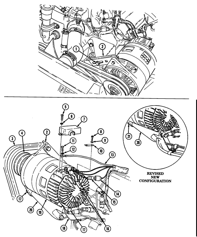 Warning
Alternator must be supported during removal and installation. Failure to support alternator may cause injury to personnel or damage to equipment.
1. Loosen capscrew (1) on alternator adjusting bracket (2) and two capscrews (17) on alternator mounting bracket (20) and support bracket (18).
2. Loosen capscrew (1) on alternator adjusting bracket (2) and nut (21) on alternator mounting bracket (20) and support bracket (18).
3. Remove two drivebelts (3) from alternator pulley (4).
4. Remove two screws (8), lockwashers (9), and wire retaining strap (10) from alternator (19). Discard lockwashers (9).
5. Remove two screws (5) and lockwashers (6) from terminal cover (7). Discard lockwashers (6).
6. Pry cover (7) away from waterproofing adhesive and remove cover (7).
7. Remove waterproofing adhesive around terminals (16).
8. Disconnect lead 568A (15) at engine wiring harness (14).
9. Remove capscrew (11) and lockwasher (12) securing ground 3B (13) to alternator (19) and disconnect ground 3B (13) from alternator (19). Discard lockwasher (12).
10. Remove nut (4), lockwasher (3), washer (2), and lead 5A (1) from alternator (9). Discard lockwasher (3).
11. Remove nut (5), lockwasher (6), washer (7), and lead 2A (8) from alternator (9). Discard lockwasher (6).
12. Remove capscrew (13), lockwasher (12), and washer (11) from adjusting bracket (10) and alternator (9). Discard lockwasher (12).

> Note
- Perform step 14 for vehicles with new alternator support bracket configuration.
- Perform step 15 for vehicles with revised new configuration 16. Remove alternator (9). 17. Remove alternator pulley (19) (para. 4-3).
B. Installation
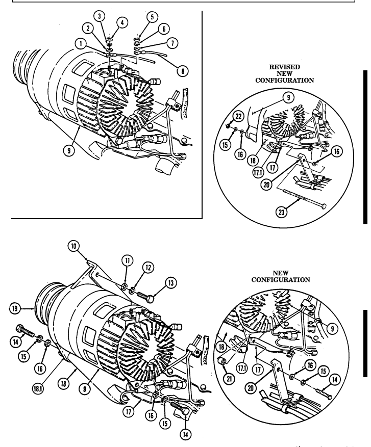 1. Install alternator pulley (19) (para. 4-3).
2. Position alternator (9) on mounting bracket (18) with support bracket (17) between mounting flange (18.1) and alternator (9) and install two washers (16), lockwashers (15), and capscrews (14).
3. Position alternator (9) on mounting bracket (18) with support bracket (17) and power steering lines bracket (20) on the outside of alternator mounting flange (17.1) and install spacer (21) between mounting bracket (18) and alternator mounting flange (17.1) with two lockwashers (15), washers (16), and capscrews (14).
4. Position alternator (9) on mounting bracket (18) with support bracket (17) and power steering lines bracket (20) on the outside of alternator mounting flange (17.1) and install washer (16), long capscrew (23), lockwasher (15), washer (16), and nut (22).
5. Align alternator (9) with adjusting bracket (10) and install washer (11), lockwasher (12), and capscrew (13).
6. Connect lead 2A (8) on alternator (9) with washer (7), lockwasher (6), and nut (5). Tighten nut (5) to 20-25 lb-in. (2-3 N•m).
7. Connect lead 5A (1) on alternator (9) with washer (2), lockwasher (3), and nut (4). Tighten nut (4) to 45-55 lb-in. (5-6 N•m).
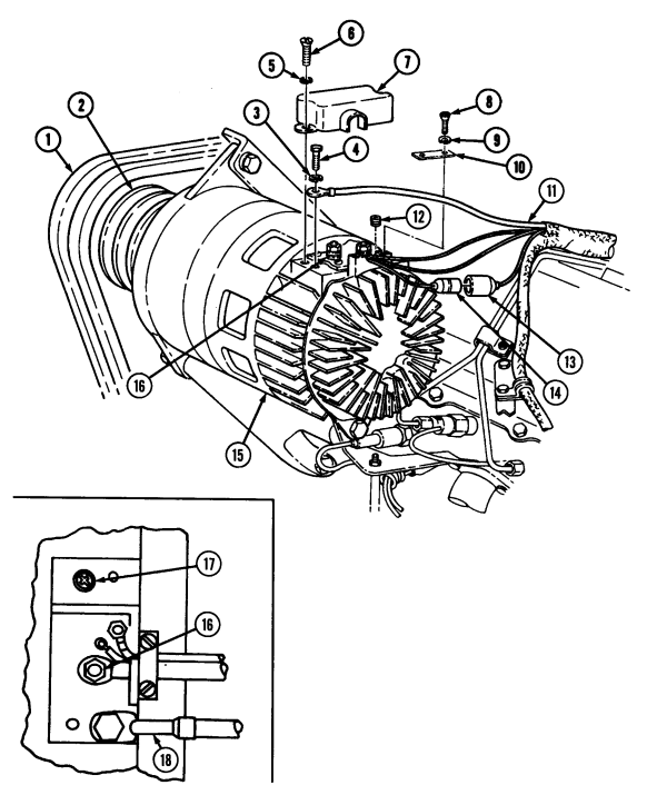
8. Connect ground 3B (11) to alternator (15) with lockwasher (3) and capscrew (4). Tighten capscrew (4)
to 82-102 lb-in. (9-12 N•m ) .
9. Connect lead 568A (14) to engine wiring harness (13).
10. Install wire retainer strap (10) on alternator (15) with two lockwashers (9) and screws (8). Tighten screws (8) to 30-35 lb-in. (3-4 N•m).
11. Install two drivebelts (1) on alternator pulley (2).
12. Adjust drivebelts (1) (para. 3-82). 13. Check alternator (15) for correct output voltage adjustment (para. 4-2, task c.).
13. Remove two capscrews (14), lockwashers (15), and washers (16) from alternator (9), support bracket (17), and mounting bracket (18). Discard lockwashers (15).
14. Remove two capscrews (14), lockwashers (15), washers (16), spacer (21), power steering lines bracket (20), and support bracket (17) from mounting bracket (18). Discard lockwashers (15).
15. Remove nut (22), lockwasher (15), washer (16), long capscrew (23), washer (16), power steering lines bracket (20), and support bracket (17) from mounting bracket (18) and alternator (9). Discard lockwasher (15).
C. Adjustment Note
Battery ground cable must be removed (para. 4-73).
-
Using hex-head driver, remove pipe plug (12). 2. Connect battery ground cable (para. 4-73). 3. Start engine (TM 9-2320-280-10). 4. Raise engine speed above idle. 5. Put a load on the alternator by operating driving lights (TM 9-2320-280-10). 6. Using a multimeter, check alternator (15) output voltage. Connect black test lead to ground lead 3B (18). Connect red test lead to lead 5A (16). Output voltage should be 28 volts ± 0.5 volts. If adjustment is required, go to step 7. If no adjustment is required, go to step 11.
-
Turn adjusting screw (17) counterclockwise to increase voltage or clockwise to decrease voltage. 8. Turn off driving lights (TM 9-2320-280-10). 9. Return engine to idle.
-
Stop engine (TM 9-2320-280-10).
-
Apply sealing compound to pipe plug (12) threads. Using hex-head driver, install pipe plug (12) and tighten to 30-40 lb-in. (3-4 N•m).
-
Remove battery ground cable (para. 4-73). 13. Seal terminal connections using adhesive sealant. 14. Install terminal cover (7) on alternator (15) with two lockwashers (5) and screws (6).
FOLLOW-ON TASKS: - Connect battery ground cable (para. 4-73).
- • - Lower and secure hood (TM 9-2320-280-10).
4-2.1. 60 Ampere Alternator Regulator Replacement
This task covers: INITIAL SETUP: Tools ____ General mechanic's tool kit: automotive (Appendix B, Item 1) Materials/Parts ____________ O-ring (Appendix G, Item 218) a. Removal
Regulator is part of end cover. Do not disassemble.
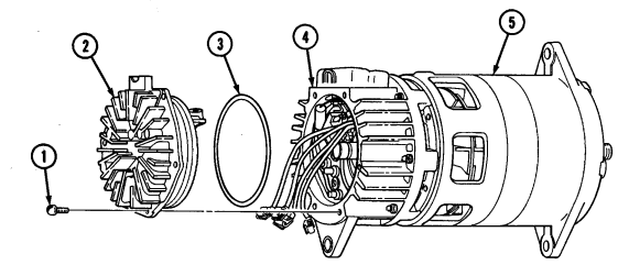
- Remove six screws (1), end cover (2), and O-ring (3) from end housing (4). Discard O-ring (3). 2. Disconnect four leads (6) from terminals (7) on regulator (8).
B. Installation
- Install O-ring (3) on end cover (2). 2. Connect four leads (6) to terminals (7) on regulator (8). 3. Install end cover (2) on end housing (4) with six screws (1). 4. Check alternator (5) for correct output voltage (para. 4-2, task c.).
a. Removal b. Installation
Manual References ________________ TM 9-2320-280-24P Equipment Condition __________________ 60 ampere alternator removed (para. 4-2).
4-2.1. 60 Ampere Alternator Regulator Replacement (Cont'D)
.
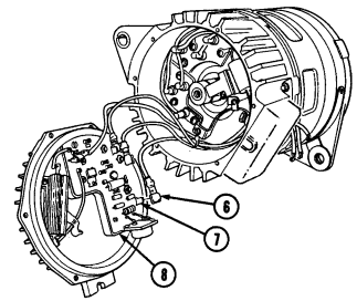
FOLLOW-ON TASK: Install alternator (para. 4-2).
4-2.2. 100/200 Ampere Alternator Cable Replacement
This task covers:
Initial Setup: Tools
General mechanic's tool kit: automotive (Appendix B, Item 1) Maintenance and repair shop equipment: automotive (Appendix B, Item 2)
Materials/Parts
Sealant (Appendix C, Item 47.1) Two lockwashers (Appendix G, Item 134) Five lockwashers (Appendix G, Item 191) Six tiedown straps (Appendix G, Item 312) a. Removal a. Removal d. 12-Volt Regulator Cable Installation b. Installation e. 100/200 Ampere Alternator Ground Cable Removal c. 12-Volt Regulator Cable Removal f. 100/200 Ampere Alternator Ground Cable Installation
Manual Reeferences
TM 9-2320-280-10 TM 9-2320-280-24P
Equipment Condition
-
Hood raised and secured (TM 9-2320-280-10). - Battery ground cables disconnected (para. 4-73). - Engine access cover removed (para. 10-15).
-
Prior to removal, tag leads for installation. - Note number of clamps and tiedown straps for installation.
-
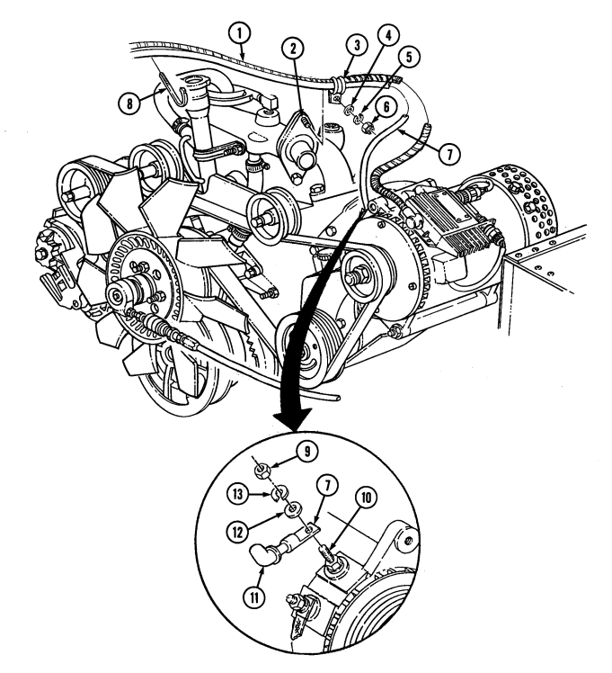
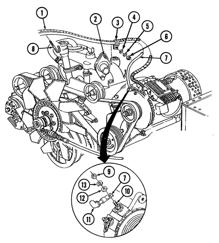
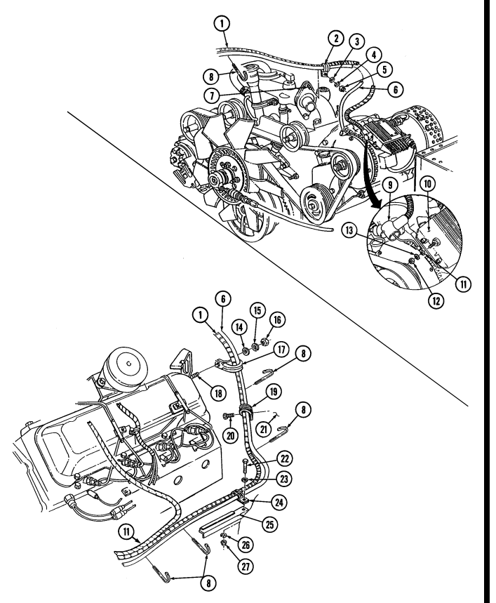
Slide back rubber boot (11) and remove nut (9), lockwasher (13), washer (12), and cable (7) from positive stud (10). Discard lockwasher (13).
-
Remove nut (6), lockwasher (5), washer (4), and clamp (3) from water crossover stud (2). Discard lockwasher (5).
-
Remove two tiedown straps (8) from cables (1) and (7). Discard tiedown straps (8).
4-2.2. 100/200 Ampere Alternator Cable Replacement(Cont'D)
4-2.2. 100/200 Ampere Alt E R N Ator Cable Replacement ( Co N T ' D )
-
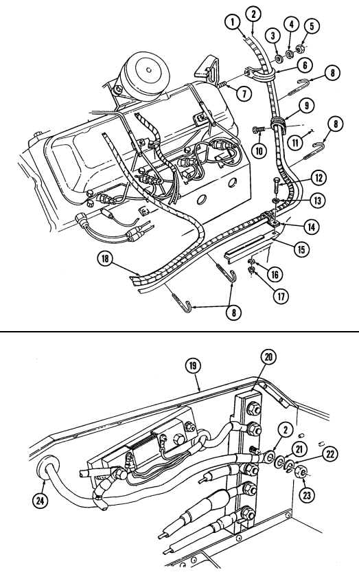
Remove nut (5), lockwasher (4), washer (3), clamp (6), and cables (1) and (2) from stud (7). Discard lockwasher (4).
-
Remove four tiedown straps (8) from cables (1), (2), and (18). Discard tiedown straps (8). 6. Remove screw (10), clamp (9), nut (17), lockwasher (16), screw (12), washer (13), and clamp (14) from bracket (15) and body (11). Discard lockwasher (16).
-
Remove nut (23), lockwasher (22), washer (21), and cable (2) from buss bar (20). Discard lockwasher (22).
-
Remove cable (2) through grommet (24) on battery box (19).
B. Installation
-
Insert cable (2) through grommet (24) on battery box (19) and install cable (2) on buss bar (20) with washer (21), lockwasher (22), and nut (23).
-
Install cables (1) and (2) on bracket (15) and body (11) with clamp (14), washer (13), screw (12), lockwasher (16), nut (17), clamp (9), and screw (10).
-
Install cables (1) and (2) on stud (7) with clamp (6), washer (3), lockwasher (4), and nut (5). 4. Secure cables (1), (2), and (18) together using four tiedown straps (8).
4-2.2. 100/200 AMPERE ALTERNATOR CABLE REPLACEMENT(Cont'd)
4-2.2. 100/200 Ampere Alt E R N Ator Cable Replacement ( Co N T ' D )
-
Install two tiedown straps (8) on cables (1) and (7). 6. Install cables (1) and (7) on water crossover stud (2) with clamp (3), washer (4), lockwasher (5), and nut (6). Tighten nut (6) to 10-15 lb-ft (14-20 N•m).
-
Apply sealant to positive stud (10) and cable (7), coating all exposed metallic surfaces. 8. Install cable (7) on positive stud (10) with washer (12), lockwasher (13), and nut (9). Tighten nut (9) to 10-15 lb-ft (14-20 N•m).
-
Slide rubber boot (11) on cable (7).
4-2.2. 100/200 Ampere Alternator Cable Replacement(Cont'D)
4-2.2. 100/200 Ampere Alt E R N Ator Cable Replacement ( Co N T ' D )
c. 12-Volt Regulator Cable Removal
- Prior to removal, tag leads for installation. - Note number of clamps and tiedown straps for installation.
-
Slide back rubber boot (9) and remove nut (12), washer (13), and cable (11) from regulator (10). 2. Remove six tiedown straps (8) from cables (1), (6), and (11). Discard tiedown straps (8). 3. Remove nut (5), lockwasher (4), washer (3), clamp (2), and cables (1) and (6) from stud (7). Discard lockwasher (4).
-
Remove nut (16), lockwasher (15), washer (14), clamp (17), and cables (1) and (6) from stud (18).
Discard lockwasher (15).
- Remove screw (20), clamp (19), nut (27), lockwasher (26), screw (22), washer (23), clamp (24), and cables (1) and (6) from bracket (25) and body (21). Discard lockwasher (26).
4-2.2. 100/200 Ampere Alternator Cable Replacement(Cont'D)
4-2.2. 100/200 Ampere Alt E R N Ator Cable Replacement ( Co N T ' D )
-
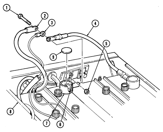
Remove cap (9) from battery terminal boot (7) and clean lubricating oil from battery terminal boot (7).
-
Remove nut (5), screw (1), and cables (2), (3), and (4) from terminal clamp (6) and battery box (8).
D. 12-Volt Regulator Cable Installation
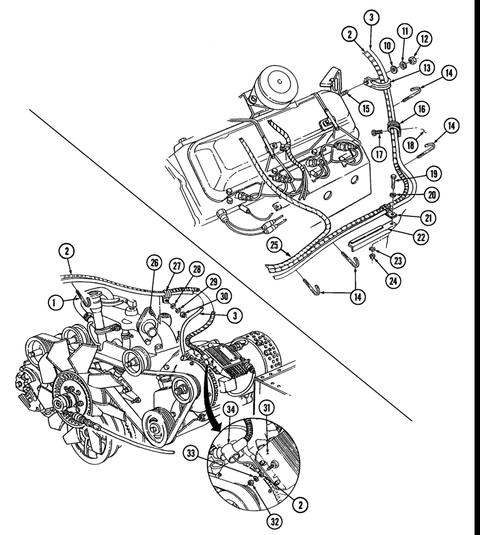
- Position cable (2) in approximate mounting location through hole in battery box (8). 2. Install cables (4), (3), and (2) on terminal clamp (6) with screw (1) and nut (5). 3. Fill battery terminal boot (7) with lubricating oil. 4. Install cap (9) on terminal boot (7). 5. Install cables (2) and (3) and clamps (16) and (21) on bracket (22) and body (18) with washer (20),
screw (19), lockwasher (23), nut (24), and screw (17).
-
Install clamp (13) and cables (2) and (3) on stud (15) with washer (10), lockwasher (11), and nut (12).
-
Install six tiedown straps (14) on cables (2), (3), and (25). 8. Install cables (2) and (3) on stud (26) with clamp (27), washer (28), lockwasher (29), and nut (30). 9. Install cable (2) on regulator (31) with washer (33) and nut (32). Tighten nut (32) to 18-22 lb-in.
(2.0-2.5 N•m). Slide rubber boot (34) on nut (32).
4-2.2. 100/200 Ampere Alternator Cable Replacement(Cont'D)
4-2.2. 100/200 Ampere Alt E R N Ator Cable Maintenance( Co N T ' D )
e. 100/200 Ampere Alternator Ground Cable Removal
-
Routing of the 200 amp ground cable is identical to the 100 amp ground cable, with the exception of the 200 amp ground cable being installed on the alternator with a washer, lockwasher, and nut. This procedure covers the 100 amp ground cable.
-
Prior to removal, tag leads for installation.
-
Slide back rubber boot (10) and remove capscrew (6), lockwasher (7), washer (8), and ground cable (4) from alternator (9). Discard lockwasher (7).
-
Remove nut (1), lockwasher (2), washer (3), ground cable (4), and washer (3) from water crossover stud (5). Discard lockwasher (2).
F. 100/200 Ampere Alternator Ground Cable Installation
-
Install washer (3), ground cable (4), washer (3), lockwasher (2), and nut (1) on water crossover stud (5).
-
Install ground cable (4) on alternator (9) with washer (8), lockwasher (7), and capscrew (6). Tighten capscrew (6) to 8-12 lb-ft (11-16 N•m).
-
Slide rubber boot (10) on capscrew (6).
4-2.2. 100/200 Ampere Alt E R N Ator Cable Replacement ( Co N T ' D )
FOLLOW-ON TASKS: - Connect battery ground cables (para. 4-73).
- Install engine access cover (para. 10-15). - Lower and secure hood (TM 9-2320-280-10).
4-3. Alternator Pulley Replacement
This task covers: INITIAL SETUP:
Tools
General mechanic's tool kit: automotive (Appendix B, Item 1) Mechanical puller (Appendix B, Item 167) Vise inserts (Appendix B, Item 170)
Materials/Parts
Locknut (Appendix G, Item 73) (60, 100 amp only) Woodruff key (Appendix G, Item 321) (60, 100 amp only) Locknut (Appendix G, Item 73.1) (200 amp - Niehoff) Woodruff key (Appendix G, Item 322) (200 amp - Niehoff)
A. Removal B. Installation
Manual References TM 9-2320-280-24P Equipment Condition
-
60 amp alternator removed (para. 4-2). - 100 amp alternator removed (para. 12-23 or 12-24).
-
200 amp alternator removed (para. 4-109 or 4-110).
The removal and installation procedure for 60 amp, 100 amp, and 200 amp alternator pulleys are identical.
A. Removal
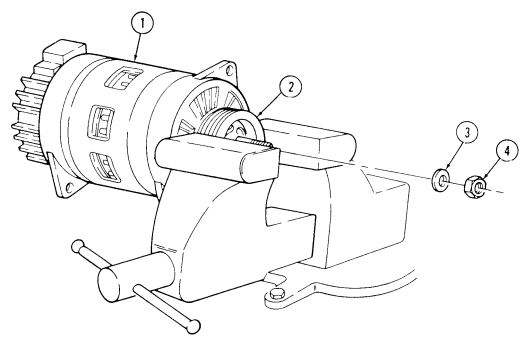
- Clamp alternator pulley (2) in a soft-jawed vise. 2. Remove locknut (4) and washer (3) from alternator shaft (6). Discard locknut (4). 3. Remove alternator (1) and pulley (2) from soft-jawed vise. 4. Using a mechanical puller, remove pulley (2) and woodruff key (5) from alternator (1). Discard woodruff key (5).
B. Installation
-
Position woodruff key (5) in alternator shaft (6) with flat side up. 2. Align pulley keyway (7) with woodruff key (5) in alternator shaft (6) and tap pulley (2) onto shaft (6).
-
Install washer (3) and locknut (4) on shaft (6). Tighten locknut (4) finger-tight. 4. Clamp pulley (2) in soft-jawed vise.
For 200 amp alternators (12447109 or 12338796-1), tighten locknut to 115-125 lb-ft (156-169 N•m).
- Tighten locknut (4) to 95 ± 5 lb-ft (129 ± 7 N•m). 6. Remove pulley (2) and alternator (1) from vise.
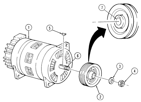
FOLLOW-ON TASKS: - Install 60 amp alternator (para. 4-2).
· Install 100 amp alternator (para. 12-23 or 12-24).
- Install 200 amp alternator (para. 4-109 or 4-110).
4-3. Alternator Pulley Replacement (Cont'D) 4-4. Alternator Mounting Brackets Replacement
This task covers:
| INITIAL SETUP: |
|---|
| Materials/Parts |
|---|
Tools General mechanic's tool kit: automotive (Appendix B, Item 1) Two lockwashers (Appendix G, Item 133) Two bolts (Appendix G, Item 5) Bolt (Appendix G, Item 4) Lockwasher (Appendix G, Item 191) Lockwasher (Appendix G, Item 178) a. Removal
A. Removal B. Installation
| One mechanic | One assistant |
|---|---|
| TM 9-2320-280-10 |
If the connection is loose between alternator bracket and alternator, tightening mounting bolts further may cause alternator bracket to fail. Notify DS maintenance to modify an older bracket.
-
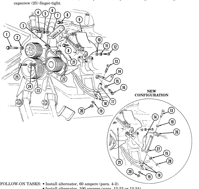
Remove capscrew (4), lockwasher (5), washer (6), and alternator adjusting bracket (7) from alternator mounting bracket (9). Discard lockwasher (5).
-
Remove bolt (1) and lockwasher (2) from power steering bracket (3), alternator mounting bracket (9), and engine (21). Discard lockwasher (2) and bolt (1).
-
Remove capscrew (12), lockwasher (11), and washer (10) from alternator mounting bracket (9) and power steering bracket (3). Discard lockwasher (11).
-
Remove capscrew (25), lockwasher (24), and washer (23), and swing power steering pump (22) down. Discard lockwasher (24).
-
Remove two bolts (8) and alternator mounting bracket (9) from engine (21). Discard bolts (8).
NOTE Perform steps 8 and 9 for vehicles with new alternator support bracket configuration.
-
Remove nut (20), washer (19), capscrew (13), spacer (17), and clamps (18) from support bracket (14). 7. Remove socket-head screw (16), washer (15), and support bracket (14) from engine (21). 8. Remove nut (20), two washers (19), capscrew (13), power steering lines bracket (27), and harness clamp (26) from clamps (18).
-
Remove nut (16), washer (15), and support bracket (14) from engine (21).
b. Installation
Perform steps 3 and 4 for vehicles with new alternator support bracket configuration.
-
Install support bracket (14) on engine (21) with washer (15) and socket-head screw (16). Tighten socket-head screw (16) to 25-33 lb-ft (34-45 N•m).
-
Install spacer (17) and clamps (18) on support bracket (14) with capscrew (13), washer (19), and nut (20).
-
Install support bracket (14) on engine (21) with washer (15) and nut (28). Tighten nut (28) to 35 lb-ft (47 N•m).
-
Install power steering lines bracket (27) and harness clamp (26) on clamps (18) with washer (19), capscrew (13), washer (19), and nut (20).
4-4. Alternator Mounting Brackets Replacement (Cont'D)
Install alternator mounting bracket (9) on engine (21) with two bolts (8). Tighten bolts (8) 5.
to 48 lb-ft (65 N.m).
Install power steering bracket (3) on alternator mounting bracket (9) with washer (10), lockwasher (11), and capscrew (12). Tighten capscrew (12) finger-tight.
Secure power steering bracket (3) on alternator mounting bracket (9) and engine (21) with lockwasher (2) and bolt (1). Tighten bolt (1) to 48 lb-ft (65 N-m). Install alternator adjusting bracket (7) on alternator mounting bracket (9) with washer (6), 8.
lockwasher (5), and capscrew (4).
Install washer (23), lockwasher (24), and capscrew (25) in power steering bracket (3). Tighten
· Install alternator, 100 ampere (para. 12-23 or 12-24). · Install alternator, 200 ampere (para. 4-109 or 4-110).
1
4-4.1. Alternator/Power Steering Mounting Bracket Replacement
This task covers: INITIAL SETUP: Applicable Models
| M1045A2, M1097A2, M1123 | Three lockwashers (Appendix G, Item 190) |
|---|---|
| Tools | Equipment Condition |
| General mechanic's tool kit: | - Fan drive and fan blade removed (para. 3-78). |
| automotive (Appendix B, Item 1) | - Serpentine drivebelt removed (para. 3-83). |
a. Removal b. Installation
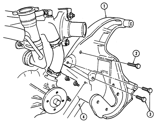
Manual References a. Removal Remove two short bolts (3), long bolt (2), and mounting bracket (1) from engine (4).
b. Installation Install mounting bracket (1) on engine (4) with two short bolts (3) and long bolt (2). Tighten bolts (3) and (2) to 48 lb-ft (65 N•m).
4-4.1. Alternator/Power Steering Mounting Bracket Replacement (Cont'D)
FOLLOW-ON TASKS: - • Install power steering pump (para. 8-24).
· Install tensioner, idler pulleys, and mounting hardware (para. 3-84). · Install 200 ampere alternator (para. 4-109 or 4-110).
4-5. Protective Control Box Maintenance
This task covers: b. Inspection
Initial Setup:
Tools General mechanic's tool kit: automotive (Appendix B, Item 1) Materials/Parts Silicone compound (Appendix C, Item 48) Personnel Required One mechanic One assistant Manual References TM 9-2320-280-10 TM 9-2320-280-24P Equipment Condition
- Battery ground cable disconnected (para. 4-73). - Hood raised and secured (TM 9-2320-280-10).
The control box must be supported from inside the vehicle during removal and installation or damage to protective control box/unit may result.
A. Removal
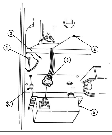
- Working under hood, disconnect engine wiring harness cannon plug (6) from control box (5). 2. From inside the vehicle, disconnect body wiring harness cannon plug (3) from control box (5). 3. Remove four screws (1) and control box (5) from cowl (2).
B. Inspection
Inspect rivnuts (5.1) for damage. Replace rivnuts (5.1) if damaged (para. 10-66).
C. Installation
-
Position control box (5) under instrument panel (4) against cowl (2). 2. From under hood, install control box (5) on cowl (2) with four screws (1). Tighten screws (1) to 6 lb-ft (8 N•m).
-
Fill engine wiring cannon plug (6) and control box connection (5) to capacity with silicone. 4. From inside vehicle, connect body wiring harness cannon plug (3) to control box (5). 5. Connect engine wiring harness cannon plug (6) to control box (5).
a. Removal c. Installation
4-5. Protective Control Box Maintenance (Cont'D)
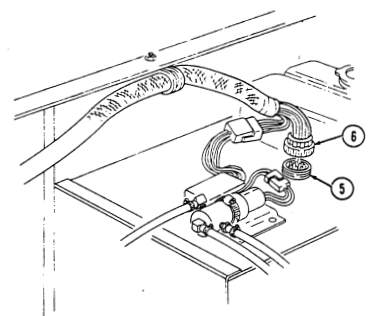
FOLLOW-ON TASKS: - Lower and secure hood (TM 9-2320-280-10).
- Connect battery ground cable (para. 4-73).
4-5.1. Distribution Box Maintenance
This task covers: b. Inspection INITIAL SETUP: Tools General mechanic's tool kit: automotive (Appendix B, Item 1) Personnel Required One mechanic One assistant a. Removal c. Installation Manual References TM 9-2320-280-10 TM 9-2320-280-24P Equipment Condition
- Battery ground cable disconnected (para. 4-73). - Hood raised and secured (TM9-2320-280-10).
The distribution box must be supported from inside the vehicle during removal and installation, or damage to distribution box may result.
a. Removal 1. From inside the vehicle, disconnect body wiring harness cannon plug (3) from distribution box (4). 2. Working under hood, disconnect engine wiring harness cannon plug (6) and glow plug wiring harness cannon plug (7) from distribution box (4).
- Remove four screws (1) and distribution box (4) from cowl (2).
b. Inspection Inspect rivnuts (5) for damage. Replace rivnuts (5) if damaged (para. 10-66).
c. Installation 1. From under hood, install distribution box (4) on cowl (2) with four screws (1). Tighten screws (1) to 71 lb-in. (8 N•m).
- Connect body wiring harness cannon plug (3) to distribution box (4). 3. Connect engine wiring harness cannon plug (6) to distribution box (4). 4. Connect glow plug wiring harness cannon plug (7) to distribution box (4).
4-5.1. Distribution Box Maintenance (Cont'D)
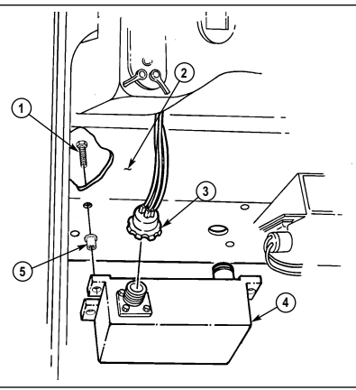
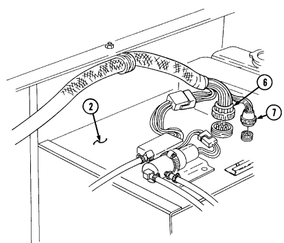
FOLLOW-ON TASKS: - Lower and secure hood (TM 9-2320-280-10).
- Connect battery ground cable (para. 4-73).
Section I.1. Dual Voltage Alt E R N Ator And Regulator System Maintenance
4 - 5 . 2 . DUAL VOLTAGE ALT E R N ATOR AND REGULATOR SYSTEM MAINTENANCE TA S K S U M M A RY
| Section I. | GENERATING AND PROTECTIVE CONTROL BOX SYSTEM MAINTENANCE | ||||
|---|---|---|---|---|---|
| 4-1. | GENERATING AND PROTECTIVE CONTROL BOX SYSTEM MAINTENANCE | TASK SUMMARY | |||
| TASK | PAGE | PROCEDURES | PARA. | NO. | |
| 4-2. | 60 Ampere Alternator Maintenance | 4-2 | |||
| 4-2.1. | 60 Ampere Alternator Regulator Replacement | 4-6.2 | |||
| 4-2.2. | 100/200 Ampere Alternator Cable Replacement | 4-6.4 | |||
| 4-3. | Alternator Pulley Replacement | 4-8 | 4-4. | Alternator Mounting Brackets Replacement | 4-10 |
| 4-4.1. | Alternator/Power Steering Mounting Bracket | Replacement | 4-10.2 | ||
| 4-5. | Protective Control Box Maintenance | 4-12 | |||
| 4-5.1. | Distribution Box Maintenance | 4-12.2 |
4-5.3. 100 Ampere Dual Voltage Alternator (12447110) Replacement
This task covers: INITIAL SETUP: Tools General mechanic's tool kit: automotive (Appendix B, Item 1) Maintenance and repair shop equipment: automotive (Appendix B, Item 2)
Materials/Parts
Lockwasher (Appendix G, Item 188) Two lockwashers (Appendix G, Item 172) Personnel Required One mechanic One assistant
a. Removal b. Installation
Manual References TM 9-2320-280-10 TM 9-2320-280-24P
Equipment Condition
- Hood raised and secured (TM 9-2320-280-10). - Battery ground cables disconnected (para. 4-73). - Engine access cover removed (para. 10-15). - Voltage regulator removed (para. 4-5.6).
General Safety Instructions Alternator must be supported during removal and installation.
a. Removal
Prior to removal, tag leads for installation.
-
Remove screw (5), lockwasher (6), washer (7), ground strap (8), and lead 3B (9) from ground point (11). Discard lockwasher (6).
-
Slide back rubber boot (4) and remove nut (3), washer (2), and alternator positive cable (1) from positive stud (12).
-
Loosen screw (15) on alternator adjustment bracket (16) and remove drivebelt (14) from alternator pulley (13) on alternator (10).
Alternator must be supported during removal. Failure to support alternator may cause injury to personnel or damage to equipment.
-
Remove screw (17) and washer (18) from alternator adjustment bracket (16). 5. Remove nut (19), lockwasher (20), washer (21), screw (26), washer (27), and alternator (10) from support bracket (28) and mounting bracket (29). Discard lockwasher (20).
-
Remove three capscrews (24), washers (25), bushings (22), and fan guard assembly (23) from alternator (10).
-
Remove alternator pulley (13) (para. 4-3).
4-5.3. 100 AMPERE DUAL VOLTAGE ALTERNATOR (12447110) REPLACEMENT(Cont'd)
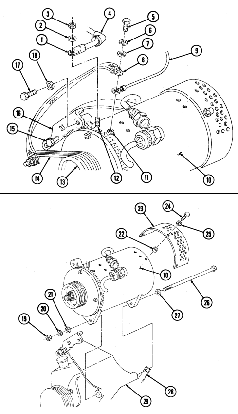
4-5.3. 100 Ampere Dual Voltage Alternator (12447110) Replacement (C O Nt' D )
b. Installation 1. Install alternator pulley (4) (para. 4-3). 2 . Install fan guard assembly (6) on alternator (11) with three bushings (5), washers (8), and capscrews (7).
Alternator must be supported during installation. Failure to support alternator may cause injury to personnel or damage to equipment.
3 . Position alternator (11) on mounting bracket (13), with support bracket (12) on outside of alternator (11), and install washer (10), capscrew (9), washer (3), lockwasher (2), and nut (1).
Note
Ensure terminals are clean before connections are made.
-
Install washer (29) and screw (28) on alternator adjustment bracket (27) and alternator (11). Do not tighten screw (28).
-
Install positive cable (14), washer (15), and nut (16) on positive stud (24). Tighten nut (16) to 10-15 lb-ft (14-20 N•m).
-
Slide rubber boot (17) over positive stud (24). 7. Install lead 3B (22) and ground strap (21) on ground point (23) with washer (20), lockwasher (19), and screw (18). Tighten screw (18) to 8-12 lb-ft (11-16 N•m).
-
Install drivebelt (25) on alternator pulley (4) and rotate alternator (11) to put tension on drivebelt (25). Tighten screws (26) and (28).
4-5.3. 100 Ampere Dual Voltage Alternator (12447110) Replacementcont'D)
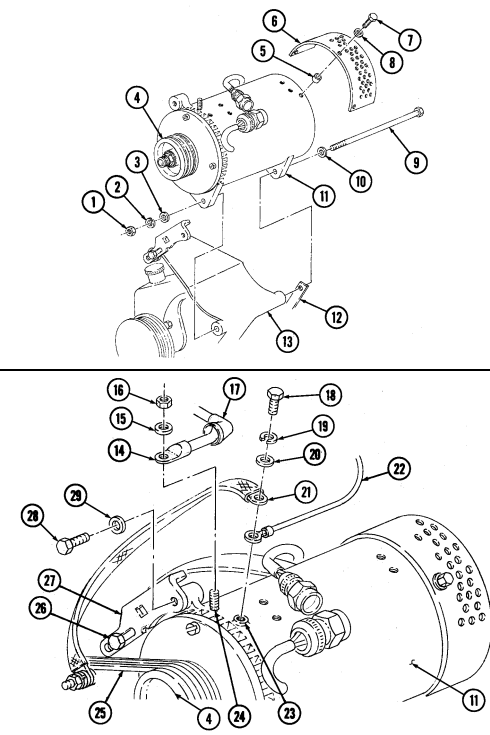
FOLLOW-ON TASKS: - • Install voltage regulator (para. 4-5.6).
· Connect battery ground cables (para. 4-73). · Install engine access cover (para. 10-15). · Lower and secure hood (TM 9-2320-280-10).
- Start engine (TM 9-2320-280-10) and check operation of voltmeter gauge.
4-5.4. 100 Ampere Dual Voltage Alternator (12447110) Cable Replacement
This task covers:
| INITIAL SETUP: |
|---|
| General mechanic's tool kit: |
|---|
| automotive (Appendix B, Item 1) |
Tools
Maintenance and repair shop equipment: automotive (Appendix B, Item 2)
Materials/Parts
Two lockwashers (Appendix G, Item 191) Silicone compound (Appendix C, Item 48) Tiedown strap (Appendix G, Item 306) Lockwasher (Appendix G, Item 134) Lockwasher (Appendix G, Item 141) a. Removal b. Installation
A. Removal B. Installation Manual References
TM 9-2320-280-10 TM 9-2320-280-24P Equipment Condition
-
Hood raised and secured (TM 9-2320-280-10).
-
Battery ground cables disconnected (para. 4-73).
-
Engine access cover removed (para. 10-15).
Prior to removal, tag leads for installation.
-
Slide back rubber boot (8) and remove nut (6), washer (7), and positive cable (1) from positive stud (9).
-
Remove nut (5), lockwasher (4), washer (3), and clamp (2) from thermostat outlet stud (10). Discard lockwasher (4).
-
Remove nut (22), lockwasher (21), clamp (20), and cable (1) from right cylinder head stud (19) of water manifold (18). Discard lockwasher (21).
-
Remove nut (17), lockwasher (16), screw (14), washer (13), and clamp (11) from inner body flange (12). Discard lockwasher (16).
-
Inspect condition of edge trim (15) for damage and replace if damaged. 6. Remove nut (28), lockwasher (27), washer (26), and cable (1) from power stud (25). Discard lockwasher (27).
-
Remove tiedown strap (24) from cable (1). 8. Remove grommet (23) and cable (1) from battery box (29) and vehicle.
Ensure studs are clean before connections are made.
-
Install grommet (23) on battery box (29). 2. Route cable (1) through grommet (23) in battery box (29) and install cable (1) on power stud (25) with washer (26), lockwasher (27), and nut (28). Apply silicone compound to power stud (25).
-
Install tiedown strap (24) on cable (1). 4. Install cable (1) on inner body flange (12) with washer (13), screw (14), clamp (11), lockwasher (16), and nut (17).
-
Install cable (1) to right cylinder head stud (19) on water manifold (18) with clamp (20), lockwasher (21), and nut (22).
-
Install cable (1) on thermostat outlet stud (10) with clamp (2), washer (3), lockwasher (4), and nut (5).
-
Install cable (1) on positive stud (9) with washer (7) and nut (6). Tighten nut (6) to 75-85 lb-ft (8-10 N•m). Slide rubber boot (8) over nut (6).
4-12.10 Change 3 4-5.4. 100 AMPERE DUAL VOLTAGE ATERNATOR (12447110) CABLE REPLACEMENT (Cont'd)
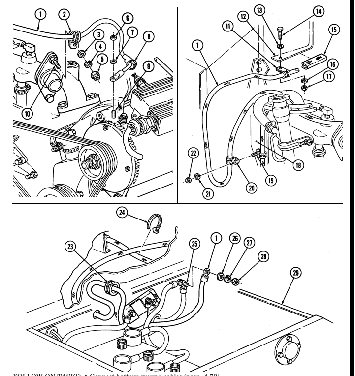
FOLLOW-ON TASKS: - Connect battery ground cables (para. 4-73). · Install engine access cover (para. 10-15).
· Lower and secure hood (TM 9-2320-280-10). - Start engine (TM 9-2320-280-10) and check operation of voltmeter gauge.
4-5.5. 100 Ampere Dual Voltage Alternator (12447110) Umbilical Power Cable Replacement
This task covers:
Intial Setup:
| Materials/Parts |
|---|
Tools General mechanic's tool kit: automotive (Appendix B, Item 1) Two lockwashers (Appendix G, Item 141) Two lockwashers (Appendix G, Item 138) Lockwasher (Appendix G, Item 148) Silicone compound (Appendix C, Item 47.1) a. Removal b. Installation a. Removal
| - 200 ampere alternator removed (para. 4-109 | or 4-110). |
|---|---|
| - Tensioner, idler pulleys, and mounting | hardware removed (para. 3-84). |
| - Power steering pump removed (para. 8-24). |
Prior to removal, tag leads for installation.
- Remove nut (5), lockwasher (4), washer (3), and positive power cable (2) from power stud (1).
Discard lockwasher (4).
- Remove capscrew (6), lockwasher (7), negative power cable (8), and two cables (9) from shunt (10).
Discard lockwasher (7).
Perform step 4 for M1097A2 and M1123 vehicles only. Perform steps 5 and 6 for M1097 and M1097A1 vehicles only.
- Remove five capscrews (34), two washers (33), and coverplate (32) from "B" beam (12). 5. Remove three capscrews (31) from coverplate (19) and "B" beam (12). 6. Remove three nuts (17), lockwashers (16), capscrews (20), and coverplate (19) from cargo floor (18).
Discard lockwashers (16).
-
Remove two nuts (15), washers (14), capscrews (26), washers (27), and mounting bracket (24) from coverplate (19).
-
Remove nut (28), screw (23), and cover chain (21) from mounting bracket (24). 9. Remove cover (22) with cover chain (21) from umbilical power cable assembly (29).
-
Remove four nuts (30), screws (25), and mounting bracket (24) from umbilical power cable assembly (29).
-
Pull umbilical power cable assembly (29) through grommet (11) and coverplate (19) and remove from vehicle.
-
Remove grommet (11) from battery box (13).
4-5.5. 100 AMPERE DUAL VOLTAGE ATERNATOR (12447110) UMBILICAL POWER CABLE REPLACEMENT (Cont'd)
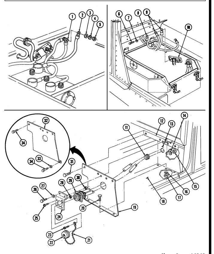
4 - 5 . 5 . 100 AMPERE DUAL VOLTAGE ALT E R N ATOR (12447110) UMBILICAL POWER
Cable Replacement (Cont'D)
b. Installation 1. Install grommet (11) on battery box (13). 2. Route umbilical power cable assembly (29) through coverplate (19) and grommet (11) and position in approximate mounting location.
-
Install mounting bracket (24) on umbilical power cable assembly (29) with three screws (25) and nuts (30).
-
Install cover (22) on umbilical power cable assembly (29). 5. Install cover chain (21) on mounting bracket (24) with screw (23) and nut (28).
Note
Perform step 6 for M1097A2 and M1123 vehicles only. Perform steps 7 and 8 for M1097 and M1097A1 vehicles.
-
Install coverplate (32) on "B" beam (12) with two washers (33) and five capscrews (34). 7 . Install mounting bracket (24) on coverplate (19) with two washers (27), capscrews (26), washers (14), and nuts (15).
-
Install coverplate (19) on "B" beam (12) with three capscrews (31). 9 . Install coverplate (19) on cargo floor (18) with three capscrews (20), lockwashers (16), and nuts (17).
Tighten nuts (17) to 65 lb-ft (88 N•m ) .
-
Install two cables (4) and negative power cable (3) on shunt (5) with lockwasher (2) and capscrew (1).
-
Install positive power cable (7) on power stud (6) with washer (8), lockwasher (9), and nut (10).
-
Apply silicone compound to cable (7), coating all exposed metallic surfaces.
4-5.5. 100 AMPERE DUAL VOLTAGE ATERNATOR (12447110) UMBILICAL POWER
CABLE REPLACEMENT (Cont'd)
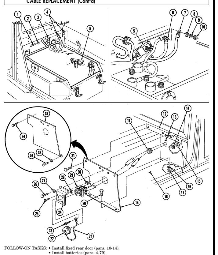
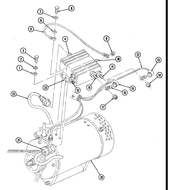
4-5.6. 100 AMPERE DUAL VOLTAGE ALTERNATOR REGULATOR (PART OF 12447110)
Replacement
This task covers: a. Removal b. Installation INITIAL SETUP: Tools General mechanic's tool kit: automotive (Appendix B, Item 1) Maintenance and repair shop equipment: automotive (Appendix B, Item 2)
Materials/Parts
Three lockwashers (Appendix G, Item 135) Lockwasher (Appendix G, Item 138) Sealant (Appendix C, Item 44) Grease (Appendix C, Item 25) Manual References TM 9-2320-280-10 TM 9-2320-280-24P Equipment Condition
- Battery ground cables disconnected (para. 4-73). - Hood raised and secured (TM 9-2320-280-10).
Prior to removal, tag leads for installation.
A. Removal
-
Disconnect voltage regulator plug (21) from voltage regulator connector (19). 2. Slide back rubber boot (13) and remove nut (14) and lead 568A (12) from IGN terminal (11). 3. Slide back rubber boot (15) and remove nut (17) and lead 2A (16) from AC terminal (18). 4. Remove nut (9) and ground wire (5) from 14-volt stud (10) on voltage regulator (23). 5. Disconnect alternator connector (22) from voltage regulator connector (4). 6. Remove screw (8), lockwasher (7), washer (6), and ground wire (5) from voltage regulator (23) and alternator (20). Discard lockwasher (7).
-
Remove three screws (3), lockwashers (2), washers (1), and voltage regulator (23) from alternator (20). Discard lockwashers (2).
B. Installation
- Install voltage regulator (23) on alternator (20) with three washers (1), lockwashers (2), and screws (3).
Tighten screws (3) to 30-34 lb-in. (3-4 N•m).
-
Install one end of ground wire (5) on voltage regulator (23) with washer (6), lockwasher (7), and screw (8). Tighten screw (8) to 88-94 lb-in. (10-11 N•m).
-
Install other end of ground wire (5) on 14-volt stud (10) with nut (9). Tighten nut (9) to 45-55 lb-in.
(5-6 N•m) and apply sealant to nut (9) and 14-volt stud (10).
-
Connect alternator connector (22) to voltage regulator connector (4). 5. Install lead 568A (12) on IGN terminal (11) with nut (14). Tighten nut (14) to 23-27 lb-in. (2.6-3.0 N•m). 6. Apply grease to IGN terminal (11), lead 568A (12), and inside of boot (13), and slide rubber boot (13) over terminal (11).
-
Install lead 2A (16) on AC terminal (18) with nut (17). Tighten nut (17) to 18-22 lb-in. (2.0-2.5 N•m). 8. Apply grease to AC terminal (18), lead 2A (16), and inside of boot (15), and slide rubber boot (15) over terminal (18).
-
Connect voltage regulator plug (21) to voltage regulator connector (19).
4-5.6. 100 AMPERE DUAL VOLTAGE ATTERNATOR REGULATOR (PART OF 12447110) REPLACEMENT (Cont'd)
FOLLOW-ON TASKS: - Connect battery ground cables (para. 4-73).
- • - • - Lower and secure hood (TM 9-2320-280-10).
17 e e e
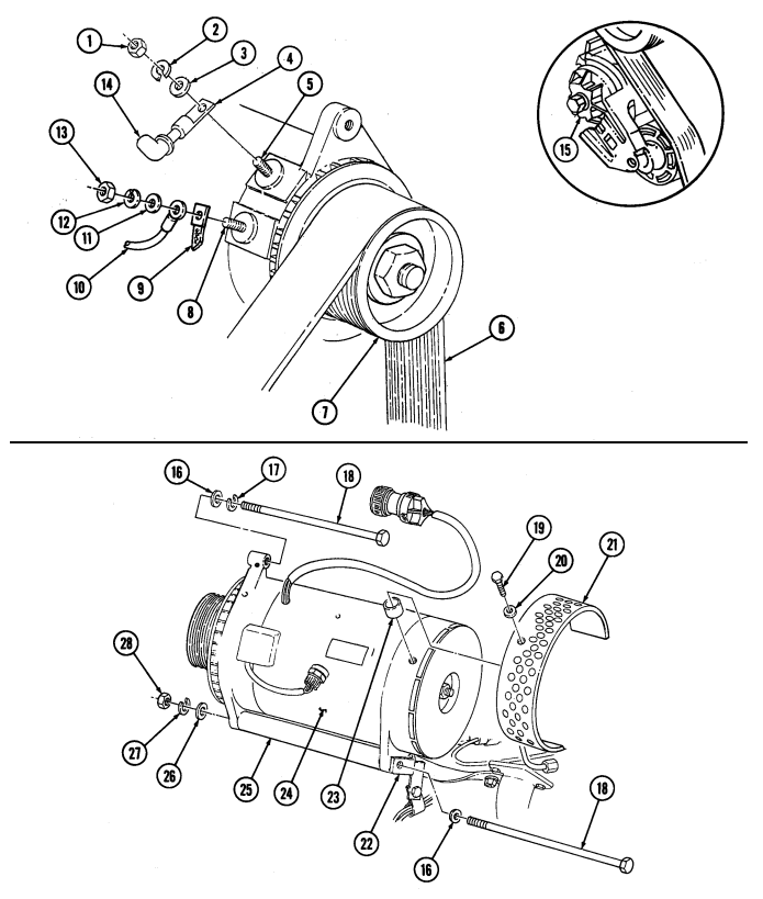
4-5.7. (6.5L) 200 Ampere Dual Voltage Alternator (12447109) Replacement
This task covers: a. Removal b. Installation
Initial Setup:
| PA R A . | P R O C E D U R E S | N O . |
|---|---|---|
| NOTE | ||
| This section pertains to vehicles configured for dual voltage and | ||
| electrical systems. Conversion from single voltage electrical | ||
| systems to dual voltage is accomplished by application of 100-, | ||
| 200-, and 400-voltage kits. Newer production vehicles incorporate | ||
| these systems. | ||
| 4-5.3. | 100 Ampere Dual Voltage Alternator (12447110) Replacement | 4-12.6 |
| 4-5.4. | 100 Ampere Dual Voltage Alternator (12447110) Cable Replacement | 4-12.10 |
| 4-5.5. | 100 Ampere Dual Voltage Alternator (12447110) Umbilical |
a. Removal
Prior to removal, tag leads for installation.
-
Remove nut (13), lockwasher (12), washer (11), lead 3B (10), and ground strap lead 3B (9) from ground stud (8). Discard lockwasher (12).
-
Slide back rubber boot (14) and remove nut (1), lockwasher (2), washer (3), and alternator positive cable lead 6 (4) from positive stud (5). Discard lockwasher (2).
-
Position 3/8-in. breaker bar on belt tensioner (15), move tensioner (15) clockwise, and remove drivebelt (6) from alternator pulley (7).
Alternator must be supported during removal. Failure to support alternator may cause injury to personnel or damage to equipment.
-
Remove nut (28), lockwasher (27), washer (26), two screws (18), washers (16), lockwasher (17), and alternator (24) from support bracket (22) and mounting bracket (25). Discard lockwashers (27) and (17).
-
Remove three capscrews (19), washers (20), bushings (23), and fan guard assembly (21) from alternator (24).
-
Remove alternator pulley (7) (para. 4-3).
4-5.7. (6.5L) 200 AMPERE DUAL VOLTAGE ALTERNATOR (12447109) REPLACEMENT (Cont'd)
4-5.7. (6.5L) 200 Ampere Dual Voltage Alternator (12447109) Replacement (Cont'D)
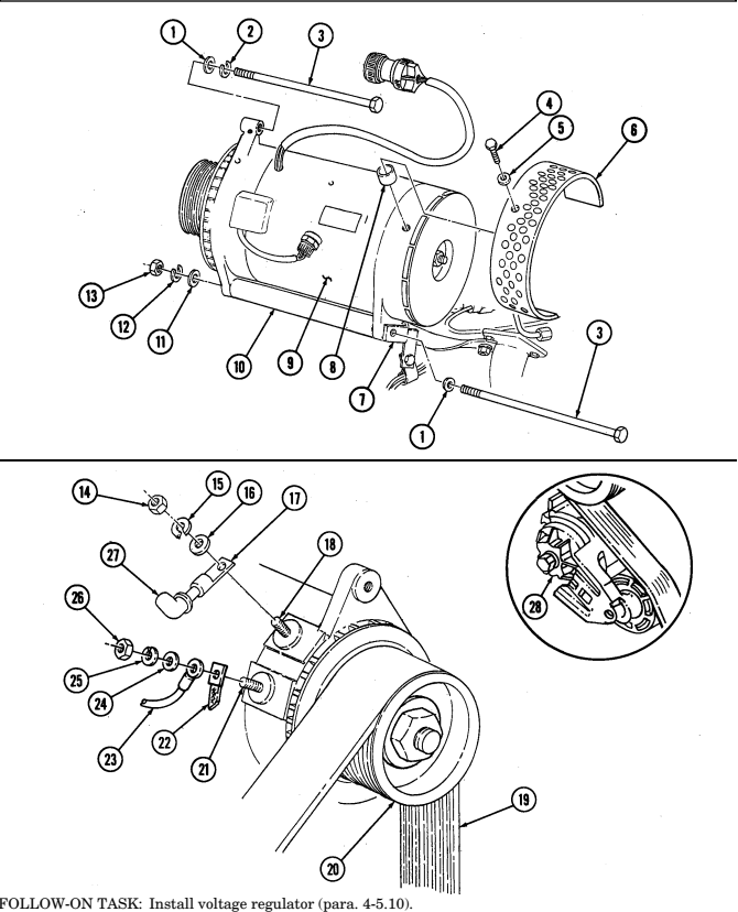
b. Installation 1. Install alternator pulley (20) (para. 4-3). 2 . Install fan guard assembly (6) on alternator (9) with three bushings (8), washers (5), and capscrews (4).
Alternator must be supported during installation. Failure to support alternator may cause injury to personnel or damage to equipment.
3 . Position alternator (9) on mounting bracket (10). 4 . Install support bracket (7) on alternator (9) and alternator mounting bracket (10) with lockwasher ( 2 ) , two washers (1), capscrews (3), washer (11), lockwasher (12), and nut (13).
Note
Ensure terminals are clean before connections are made.
-
Install positive cable lead 6 (17) on positive stud (18) with washer (16), lockwasher (15), and nut (14). Tighten nut (14) to 10-15 lb-ft (14-20 N•m).
-
Apply grease to positive terminal (18), positive cable lead 6 (17), and inside of rubber boot (27), slide boot (27) over stud (18).
-
Install ground strap (22) and lead 3B (23) on ground stud (21) with washer (24), lockwasher (25), and nut (26). Tighten nut (26) to 8-12 lb-ft (11-16 N•m).
-
Position 3/8-in. breaker bar on belt tensioner (28), move tensioner (28) clockwise, and install belt (19) on alternator pulley (20).
4-5.7. (6.5L) 200 AMPERE DUAL VOLTAGE ALTERNATOR (12447109) REPLACEMENT (Cont'd)
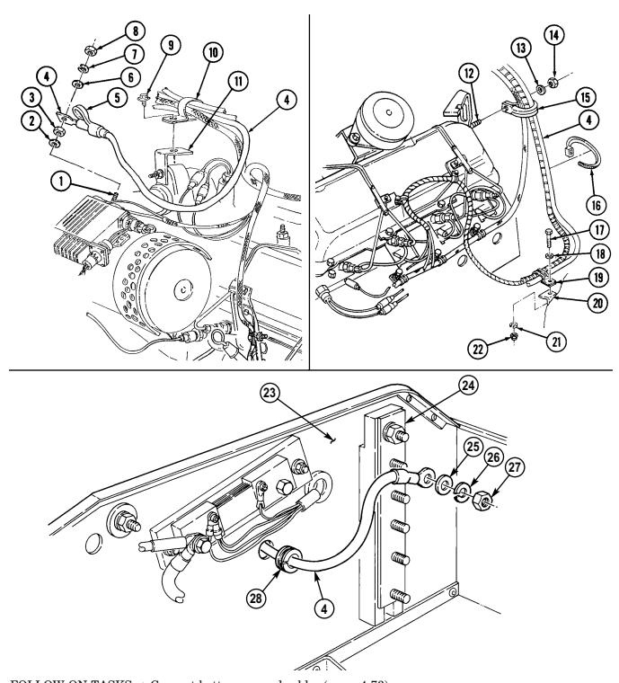
4-5.8. (6.5L) 200 Ampere Dual Voltage Alternator (12447109) Cable Replacement
This task covers:
| INITIAL SETUP: |
|---|
Tools
General mechanic's tool kit: automotive (Appendix B, Item 1) Maintenance and repair shop equipment: automotive (Appendix B, Item 2)
Materials/Parts
Four tiedown straps (Appendix G, Item 309) Lockwasher (Appendix G, Item 134) Lockwasher (Appendix G, Item 186) Lockwasher (Appendix G, Item 191) Lockwasher (Appendix G, Item 150)
| Manual References |
|---|
| TM 9-2320-280-10 |
| TM 9-2320-280-24P |
a. Removal b. Installation
Equipment Condition
- Hood raised and secured (TM 9-2320-280-10). - Battery ground cables disconnected (para. 4-73). - Engine access cover removed (para. 10-15).
A. Removal Note
Prior to removal, tag leads for installation.
-
Slide back rubber boot (5) and remove nut (8), lockwasher (7), washer (6), cable (4), nut (3), and washer (2) from positive stud (1). Discard lockwasher (7).
-
Remove capscrew (9) and clamp (10) from water crossover bracket (11), and separate cable (4) from cables and clamp (10).
-
Remove nut (14), lockwasher (13), and clamp (15) from stud (12) and separate cable (4) from cables and clamp (15). Discard lockwasher (13).
-
Remove and discard four tiedown straps (16). 5. Remove nut (22), lockwasher (21), screw (17), and washer (18) from bracket (20) and remove cable (4) from clamp (19). Discard lockwasher (21).
-
Remove nut (27), lockwasher (26), washer (25), and cable (4) from buss bar (24) on battery box (23).
Discard lockwasher (26).
- Remove cable (4) through grommet (28) and vehicle.
b. Installation
Ensure terminals are clean before connections are made.
-
Install cable (4) through grommet (28) in battery box (23). 2. Install cable (4) on buss bar (24) with washer (25), lockwasher (26), and nut (27). 3. Install four tiedown straps (16) on cable (4). 4. Route cable (4) through clamp (19), and install clamp (19) to bracket (20) with washer (18), screw (17), lockwasher (21), and nut (22).
-
Route cable (4) through clamp (15), and install clamp (15) on stud (12) with lockwasher (13), and nut (14).
-
Route cable (4) through clamp (10), and install clamp (10) on water crossover bracket (11) with capscrew (9).
-
Install washer (2), nut (3), and cable (4) on positive stud (1) with washer (6), lockwasher (7), and nut (8). Tighten nut (8) to 10-15 lb-ft (14-20 N•m), and slide rubber boot (5) over nut (8).
4-5.8. (6.5L) 200 AMPERE DUAL VOLTAGE ALTERNATOR (12447109) CABLE REPLACEMENT (Cont'd)
FOLLOW-ON TASKS: - Connect battery ground cables (para. 4-73).
· Install engine access cover (para. 10-15).
- Lower and secure hood (TM 9-2320-280-10). - Start engine (TM 9-2320-280-10) and check operation of voltmeter gauge.
4-5.9. (6.5L) 200 AMPERE DUAL VOLTAGE ALTERNATOR (12447109) UMBILICAL POWER CABLE REPLACEMENT This task covers:
| General mechanic's tool kit: |
|---|
| automotive (Appendix B, Item 1) |
| Materials/Parts |
|---|
INITIAL SETUP: Tools automotive (Appendix B, Item 1) Two lockwashers (Appendix G, Item 138) Lockwasher (Appendix G, Item 148) Lockwasher (Appendix G, Item 150) Sealing compound (Appendix C, Item 47.1) a. Removal b. Installation a. Removal
| TM 9-2320-280-10 |
|---|
| TM 9-2320-280-24P |
| Equipment Condition |
| - Hood raised and secured |
| (TM 9-2320-280-10). |
| - Battery ground cables disconnected |
| (para. 4-73). |
| - Engine access cover removed (para. 10-15). |
Prior to removal, tag leads for installation.
-
Remove nut (5), lockwasher (4), washer (3), and positive power cable (2) from buss bar (1). Discard lockwasher (4).
-
Remove capscrew (6), lockwasher (7), negative power cable (8), and two cables (9) from shunt (10).
Discard lockwasher (7).
- Remove five capscrews (20), two lockwashers (19), washers (18), and coverplate (17) from "B" beam (12).
Discard lockwashers (19).
-
Remove two nuts (15), washers (14), capscrews (25), washers (26), and mounting bracket (27) from coverplate (17).
-
Remove nut (28), screw (23), and cover chain (21) from mounting bracket (27). 6. Remove cover (22) with cover chain (21) from umbilical power cable assembly (29). 7. Remove four nuts (30), screws (24), and mounting bracket (27) from umbilical power cable assembly (29). 8. Pull umbilical power cable assembly (29) through grommet (11) and coverplate (17), and remove from vehicle (16).
-
Remove grommet (11) from battery box (13).
B. Installation
-
Install grommet (11) on battery box (13). 2. Route umbilical power cable assembly (29) through coverplate (17) and grommet (11), and position in approximate mounting location on vehicle (16).
-
Install cover chain (21) on mounting bracket (27) with screw (23) and nut (28). 4. Install umbilical power cable assembly (29) on mounting bracket (27) with four screws (24) and nuts (30).
-
Install cover (22) on umbilical power cable assembly (29). 6. Install coverplate (17) on "B" beam (12) with two washers (18), lockwashers (19), and five capscrews (20).
-
Install mounting bracket (27) on coverplate (17) with two washers (26), capscrews (25), washers (14), and nuts (15).
-
Install two cables (9) and negative power cable (8) on shunt (10) with lockwasher (7) and capscrew (6).
-
Install positive power cable (2) on buss bar (1) with washer (3), lockwasher (4), and nut (5).
-
Apply silicone compound to cable (2), coating all exposed metallic surfaces.
4-5.9. (6.5L) 200 AMPERE DUAL VOLTAGE ALTERNATOR (12447109) UMBILICAL POWER
Cable Replacement (Confd)
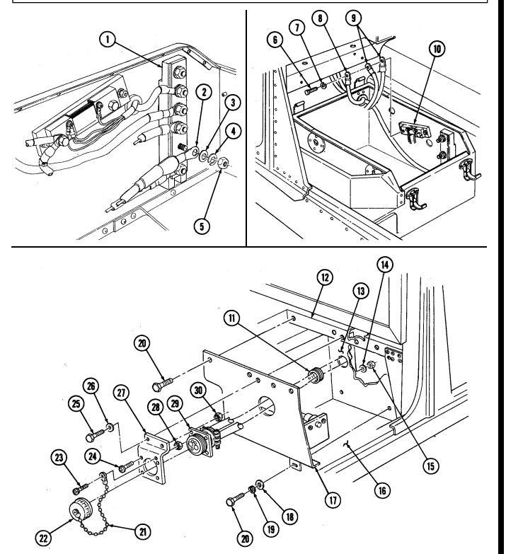
FOLLOW-ON TASKS: - Install fixed rear door (para. 10-14).
- Install batteries (para. - Install batteries (para. 4-79).
4-5.10. (6.5L) 200 Ampere Dual Voltage Regulator ( Part Of 12447109) Replacement
This task covers: a. Removal b. Installation INITIAL SETUP: Tools General mechanic's tool kit: automotive (Appendix B, Item 1) Maintenance and repair shop equipment: automotive (Appendix B, Item 2) Materials/Parts Two spring tension washers (Appendix G, Item 318) Lockwasher (Appendix G, Item 185) Grease (Appendix C, Item 25) a. Removal Manual References TM 9-2320-280-10 TM 9-2320-280-24P Equipment Condition
- Battery ground cables disconnected (para. 4-73). - Hood raised and secured (TM 9-2320-280-10).
Prior to removal, tag leads for installation.
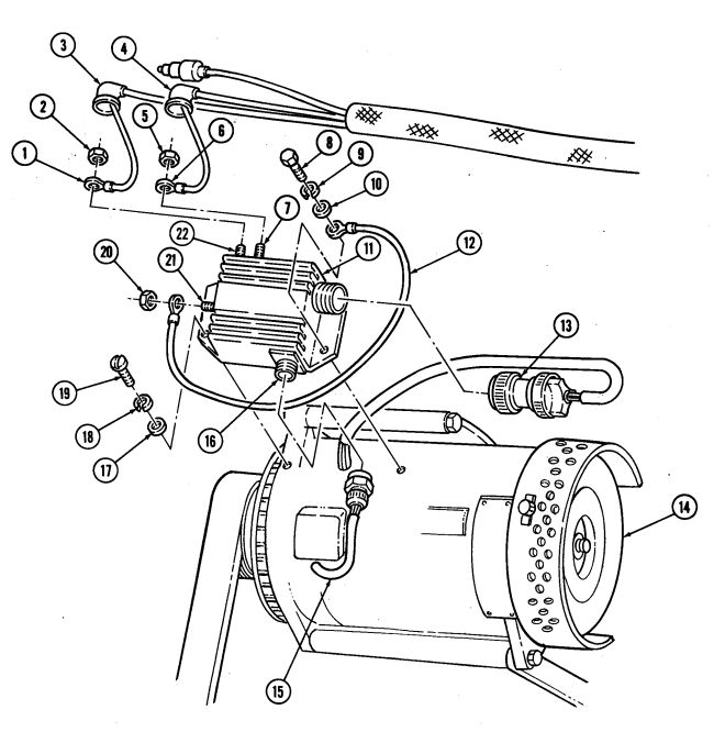
- Disconnect regulator plug (13) from voltage regulator (11). 2. Slide back rubber boot (3) and remove nut (2) and lead 5A (1) from IGN terminal (22). 3. Slide back rubber boot (4) and remove nut (5) and lead 2A (6) from AC terminal (7). 4. Remove nut (20) and ground wire (12) from 14-volt stud (21). 5. Remove screw (8), lockwasher (9), washer (10), and ground wire (12) from voltage regulator (11).
Discard lockwasher (9).
- Disconnect alternator connector (15) from regulator connector (16). 7. Remove two screws (19), spring tension washers (18), washers (17), and voltage regulator (11) from alternator (14). Discard spring tension washers (18).
B. Installation
-
Install voltage regulator (11) on alternator (14) with two washers (17), spring tension washers (18), and screws (19). Tighten screws (19) to 30-34 lb-in. (3-4 N•m).
-
Connect alternator connector (15) to regulator connector (16). 3. Install lead 5A (1) and nut (2) on IGN terminal (22). Tighten nut (2) to 23-27 lb-in. (2.6-3.0 N•m). 4. Apply grease to IGN terminal (22), lead 5A (1), and inside of boot (3), and slide boot (3) over IGN terminal (22).
-
Install lead 2A (6) and nut (5) on AC terminal (7). Tighten nut (5) to 18-22 lb-in. (2.0-2.5 N•m). 6. Apply grease to AC terminal (7), lead 2A (6), and inside of boot (4), and slide boot (4) over AC terminal (7).
-
Connect regulator plug (13) to voltage regulator (11). 8. Install one end of ground wire (12) on 14-volt stud (21) on regulator (11) with nut (20). Tighten nut (20) to 45-55 lb-in. (5-6 N•m).
-
Install other end of ground wire (12) on regulator (11) with washer (10), lockwasher (9), and screw (8). Tighten screw (8) to 88-94 lb-in. (10-11 N•m).
4-5.10. (6.5L) 200 AMPERE DUAL VOLTAGE REGULATOR ( PART OF 12447109)
Replacement (Cont'D)
FOLLOW-ON TASKS: - Connect battery ground cables (para. 4-73).
· Lower and secure hood (TM 9-2320-280-10).
4-5.11. (6.5L) 400 Ampere Dual Voltage Regulator ( Part Of 12446760) Replacement
This task covers: INITIAL SETUP: Tools General mechanic's tool kit: automotive (Appendix B, Item 1) Maintenance and repair shop equipment: automotive (Appendix B, Item 2)
Materials/Parts
Two lockwashers (Appendix G, Item 187) Lockwasher (Appendix G, Item 185) Grease (Appendix C, Item 25)
A. Removal B. Installation
Manual References TM 9-2320-280-10 TM 9-2320-280-24P Equipment Condition
- Battery ground cables disconnected (para. 4-73). - Hood raised and secured (TM 9-2320-280-10).
a. Removal
Prior to removal, tag leads for installation.
-
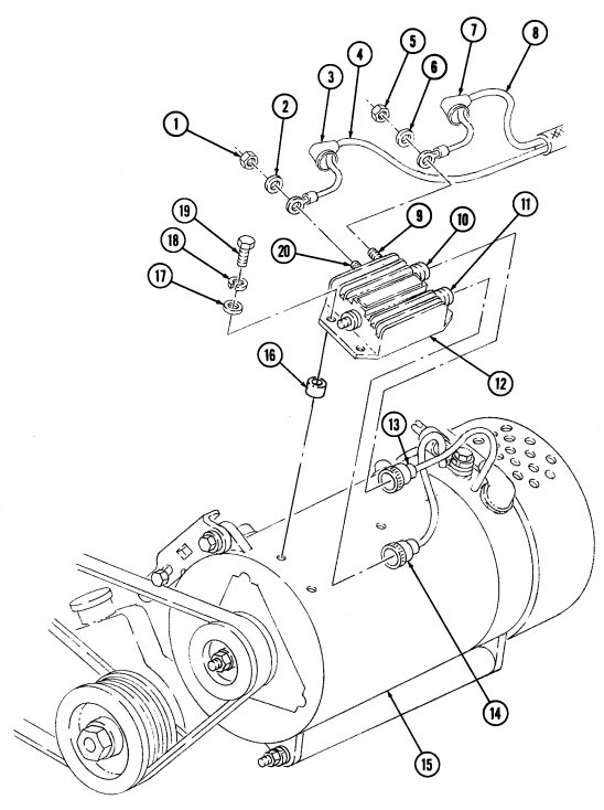
Disconnect regulator plugs (13) and (14) from connectors (10) and (11) on voltage regulator (12). 2. Slide back rubber boot (7) and remove nut (5), washer (6), and lead 5A (8) from red terminal (9) on voltage regulator (12).
-
Slide back rubber boot (3) and remove nut (1), washer (2), and lead 2A (4) from yellow terminal (20) on voltage regulator (12).
-
Remove three screws (19), lockwashers (18), washers (17), spacers (16), and voltage regulator (12) from alternator (15). Discard lockwashers (18).
B. Installation
-
Install voltage regulator (12) on alternator (15) with three spacers (16), washers (17), lockwashers (18), and screws (19) . Tighten screws (19) to 30-34 lb-in. (3-4 N•m).
-
Install lead 5A (8), washer (6), and nut (5) on red terminal (9) of voltage regulator (12). Tighten nut (5) to 35 lb-in. (4 N•m).
-
Apply grease to red terminal (9), lead 5A (8), and inside of boot (7), and slide boot (7) over red terminal (9).
-
Install lead 2A (4), washer (2), and nut (1) on yellow terminal (20) of voltage regulator (12). Tighten nut (1) to 20 lb-in. (2 N•m).
-
Apply grease to yellow terminal (20), lead 2A (4), and inside of boot (3), and slide boot (3) over yellow terminal (20).
-
Connect regulator plugs (13) and (14) to connectors (10) and (11) on voltage regulator (12).
4-5.11. (6.5L) 400 AMPERE DUAL VOLTAGE REGULATOR ( PRT OF 12446760) REPLACEMENT (Cont'd)
FOLLOW-ON TASKS: - Connect battery ground cables (para. 4-73).
· Lower and secure hood (TM 9-2320-280-10).
4-5.12. (6.5L) 400 AMPERE DUAL VOLTAGE ALTERNATOR (PART OF 12446760) CABLE
Replacement
This task covers:
Initial Setup:
Tools General mechanic's tool kit: automotive (Appendix B, Item 1) Maintenance and repair shop equipment: automotive (Appendix B, Item 2)
Materials/Parts
Locknut (Appendix G, Item 72) Three lockwashers (Appendix G, Item 191) Locknut (Appendix G, Item 79) Lockwasher (Appendix G, Item 141) Five lockwashers (Appendix G, Item 190) Three tiedown straps (Appendix G, Item 309) a. Removal a. Removal b. Installation
Manual References
TM 9-2320-280-10 TM 9-2320-280-24P Equipment Condition
-
Hood raised and secured (TM 9-2320-28010).
-
Battery ground cables disconnected (para.
4-73).
- Engine access cover removed (para. 10-15).
Prior to removal, tag leads for installation.
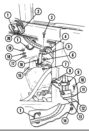
- Remove locknut (7), washer (6), screw (3), clamp (4), and cables (2) and (20) from bracket (5).
Discard locknut (7).
-
Remove nut (19), lockwasher (18), washer (17), and bracket (5) from stud (16) on right rear intake manifold (15). Discard lockwasher (18).
-
Remove screw (8), clamp (9), and cables (2) and (20) from bracket (11). 4. Remove locknut (14), washer (13), screw (10), and bracket (11) from right rear cowl (12). Discard locknut (14).
-
Remove three tiedown straps (1) from cables (2) and (20). Discard tiedown straps (1). 6. Remove nut (21), lockwasher (22), washer (23), and cable (20) from stud (31) on battery box side panel (24). Discard lockwasher (22).
-
Remove nut (28), lockwasher (29), washer (27), and cable (2) from stud (26) on buss bar (25).
Discard lockwasher (29).
- Remove grommet (30) from battery box side panel (24) and remove cable (2) through battery box side panel (24).
4-5.12. (6.5L) 400 AMPERE DUAL VOLTAGE ATERNATOR (PART OF 12446760) CABLE REPLACEMENT (Conf d)
4-5.12. (6.5L) 400 Ampere Dual Voltage Aternator (Part Of 12446760) Cable Replacement (Conf D)
Remove nut (6), screw (7), cable (2), and clamp (8) from oil pan bracket (1). Remove nut (3), lockwasher (4), and cable (2) from positive terminal (5). Discard lockwasher (4). Remove nut (11), lockwasher (12), washer (13), clamp (9), and cable (2) from stud (10) on thermostat housing (14). Discard lockwasher (12). Remove nut (15), washer (16), clamp (18), and cable (2) from stud (17).
4-5.12. (6.5L) 400 Ampere Dual Voltage Aternator (Part Of 12446760) Cable Replacement (Cont'D)
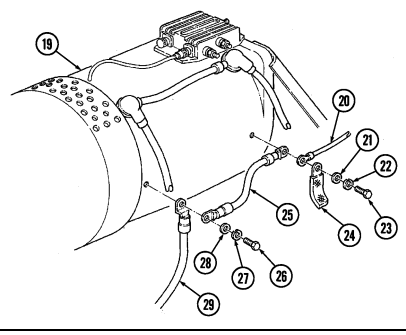
Remove screw (23), lockwasher (22), washer (21), ground strap (24), lead (20), and cable (25) from 13.
alternator (19). Discard lockwasher (22).
Remove screw (26), lockwasher (27), washer (28), cables (25) and (29) from alternator (19). Discard 14.
lockwasher (27).
Slide back rubber boot (35) and remove screw (31), lockwasher (32), washer (33), and cables (34) 15.
and (36) from alternator (19). Discard lockwasher (32). Slide back rubber boot (40) and remove screw (30), lockwasher (39), washer (38), and cables (37) 16.
and (36) from alternator (19). Discard lockwasher (39).
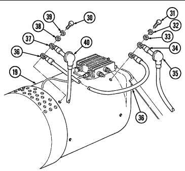
4 - 5 . 1 2 . (6.5L) 400 AMPERE DUAL VOLTAGE ALT E R N ATOR (PA RT OF 12446760) CABLE
Replacement ( C O N T ' D )
B. Installation
-
Install cables (2) and (3) to rear positive terminal (14) on alternator (1) with washer (4), lockwasher (5), and screw (6), and slide rubber boot (7) over cables (2) and (4).
-
Install cables (2) and (9) to front positive terminal (8) on alternator (1) with washer (10), lockwasher (12), and screw (11), and slide rubber boot (13) over cables (2) and (9).
-
Install ground strap (17), lead (16), and cable (21) to front negative terminal (15) on alternator (1) with washer (18), lockwasher (20), and screw (19).
-
Install cables (25) and (21) to rear negative terminal (26) on alternator (1) with washer (24),
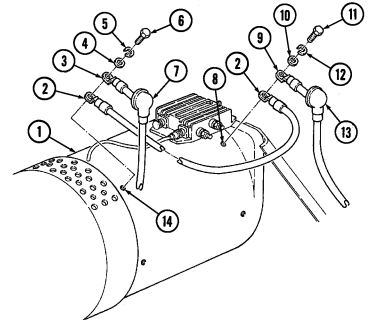
lockwasher (23), and screw (22).
4-5.12. (6.5L) 400 AMPERE DUAL VOLTAGE ATERNATOR (PART OF 12446760) CABLE
Replacement (Cont'D)
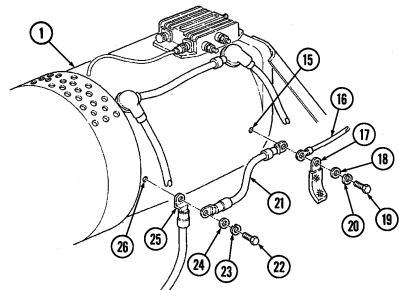
Install cable (9) on stud (35) with clamp (36), washer (34), and nut (33).
Install cable (9) to stud (28) on thermostat housing (32) with clamp (27), washer (29), lockwasher (31), and nut (30).
Install cable (9) on positive terminal (41) of starter (44) with lockwasher (39) and nut (40). Install cable (9) on oil pan bracket (38) with clamp (37), screw (43), and nut (42).
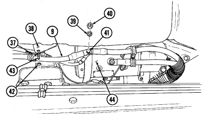
4 - 5 . 1 2 . (6.5L) 400 Ampere Dual Voltage Alt E R N Ator (Pa Rt Of 12446760) Cable Replacement ( C O N T ' D )
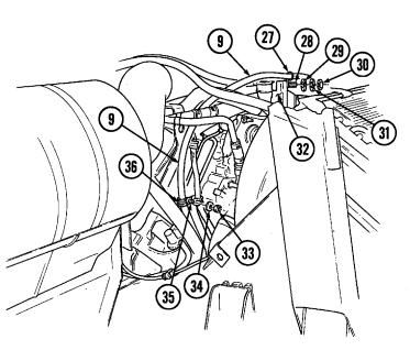
- Install grommet (12) on battery box side panel (5) and route cable (8) through grommet (12) and
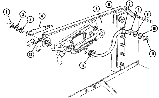
battery box side panel (5).
-
Install cable (8) to stud (7) on buss bar (6) with washer (9), lockwasher (10), and nut (11).
-
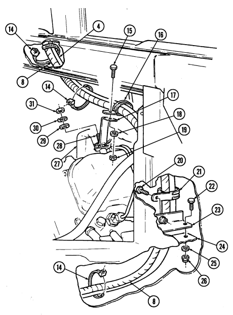
Install cable (4) to stud (13) on battery box side panel (5) with washer (3), lockwasher (2), and nut (1).
-
Install bracket (23) on right rear cowl (24) with screw (22), washer (25), and locknut (26). 13. Install cables (4) and (8) on bracket (23) with clamp (21) and screw (20). 14. Install bracket (17) to stud (28) on right rear intake manifold (27) with washer (29), lockwasher (30), and nut (31).
-
Install cables (4) and (8) on bracket (17) with clamp (16), screw (15), washer (18), and locknut (19). 16. Install three tiedown straps (14) on cables (4) and (8).
4-5.12. (6.5L) 400 AMPERE DUAL VOLTAGE ATERNATOR (PART OF 12446760) CABLE REPLACEMENT (Cont'd)
FOLLOW-ON TASKS:
- Install engine access cover (para. 10-15).
· Connect battery ground cables (para. 4-73). - Lower and secure hood (TM 9-2320-280-10).
4-5.13. (6.5L) 400 Ampere Dual Voltage Alternator (12446760) Replacement
This task covers: INITIAL SETUP: Tools General mechanic's tool kit: automotive (Appendix B, Item 1) Maintenance and repair shop equipment: automotive (Appendix B, Item 2)
Materials/Parts
Lockwasher (Appendix G, Item 191) Lockwasher (Appendix G, Item 133) Lockwasher (Appendix G, Item 151) Personnel Required One mechanic One assistant a. Removal
a. Removal b. Installation
| Personnel Required |
|---|
Equipment Condition
- Hood raised and secured (TM 9-2320-280-10). - Battery ground cables disconnected (para. 4-73). - Engine access cover removed (para. 10-15). - Alternator cables removed (para. 4-5.12).
General Safety Instructions Alternator must be supported during removal and installation.
NOTE Prior to removal, tag leads for installation.
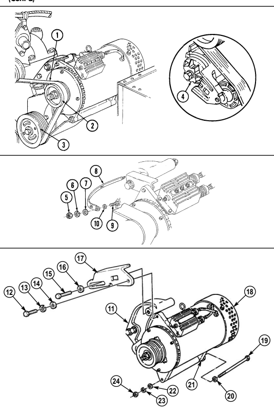
-
Position 3/8-in. breaker bar on belt tensioner (4), move tensioner (4) clockwise, and remove drivebelt (1) from power steering pump pulley (3) and alternator pulley (2).
-
Remove nut (5), lockwasher (6), washer (7), ground strap (8), and washer (10) from stud (9). Discard lockwasher (6).
Alternator must be support during removal and installation. Failure to do so may cause injury to personnel or damage to equipment.
B. Installation
-
Remove screw (12), lockwasher (13), and washer (14) from alternator bracket (17) and alternator mounting bracket (11). Discard lockwasher (13).
-
Remove screw (15), washer (16), and bracket (17) from alternator (18) and alternator mounting bracket (11).
-
Remove nut (24), lockwasher (23), washer (22), screw (19), washer (20), and alternator (18) from alternator support bracket (21) and alternator mounting bracket (11). Discard lockwasher (23).
-
Remove alternator pulley (2) (para. 4-3).
-
Install alternator pulley (2) (para. 4-3). 2. Position alternator (18) on alternator mounting bracket (11). 3. Install alternator (18) on alternator mounting bracket (11) and alternator support bracket (21) with washer (20), screw (19), washer (22), lockwasher (23), and nut (24). Do not tighten nut (24).
-
Install alternator bracket (17) on alternator mounting bracket (11) and alternator (18) with washer (16) and screw (15). Do not tighten screw (15).
-
Install washer (14), lockwasher (13), and screw (12) on alternator mounting bracket (11) and alternator bracket (17).
-
Tighten screw (15) to 40 lb-ft (54 N•m). 7. Tighten nut (24) to 155 lb-ft (210 N•m). 8. Install ground strap (8) on stud (9) with washers (10) and (7), lockwasher (6), and nut (5). 9. Position 3/8-in. breaker bar on belt tensioner (4) and move tensioner (4) clockwise and install drivebelt (1) on power steering pump pulley (3) and alternator pulley (2).
4-5.13. (6.5L) 400 AMPERE DUAL VOLTAGE ALTERNATOR (12446760) REPLACEMENT (Cont'd)
FOLLOW-ON TASKS: - Install alternator cables (para. 4-5.12).
- Install engine access cover (para. 10-15). - Connect battery ground cables (para. 4-73). - Lower and secure hood (TM 9-2320-280-10).
Section Ii. Starter And Starting Control System Maintenance
4-6. Starter And Starting Control System Maintenance Task Summary
| a. Removal | b. | Installation |
|---|---|---|
| INITIAL SETUP: | ||
| Tools | Personnel Required | |
| General mechanic's tool kit: | One mechanic | |
| automotive (Appendix B, Item 1) | One assistant | |
| Maintenance and repair shop equipment: | Manual References |
4-7. Rotary Switch Replacement
This task covers: a. Removal b. Installation
| a. Removal | |
|---|---|
| NOTE | |
| Prior to removal, tag leads for installation. | |
| 1. | Remove nut (13), lockwasher (12), washer (11), lead 3B (10), and ground strap lead 3B (9) from |
| ground stud (8). Discard lockwasher (12). | |
| 2. | Slide back rubber boot (14) and remove nut (1), lockwasher (2), washer (3), and alternator positive |
INITIAL SETUP:
Prior to removal, tag leads and note position of lever for installation.
A. Removal
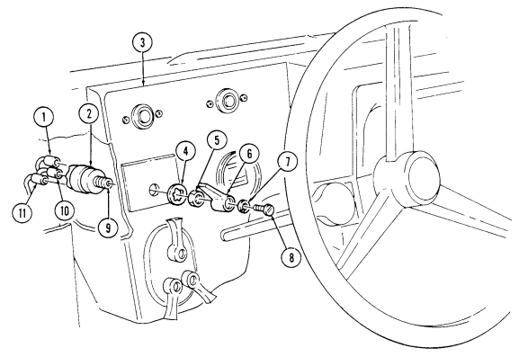
- Remove screw (8), lockwasher (7), and switch lever (6) from switch shaft (9). Discard lockwasher (7). 2. Remove nut (5) and lockwasher (4) from switch (2) and instrument panel (3). Discard lockwasher (4). 3. Push switch (2) out of hole in panel (3). 4. Disconnect three electrical leads 11A (1), 14A (10), and 29A (11) from switch (2) and remove switch (2).
B. Installation
- Connect three electrical leads 11A (1), 14A (10), and 29A (11) on switch (2). 2. Install switch (2) into hole in panel (3). 3. Install lockwasher (4) and nut (5) on switch (2). 4. Place switch lever (6) on switch shaft (9) to indicate ENGINE STOP position. 5. Secure lever (6) on switch shaft (9) with lockwasher (7) and screw (8).
4-7. Rotary Switch Replacement (Cont'D)
FOLLOW-ON TASKS: - Connect battery ground cable (para. 4-73).
- • - • Check rotary switch operation (TM 9-2320-280-10).
4-8. Starter Replacement
This task covers: INITIAL SETUP:
Tools
General mechanic's tool kit: automotive (Appendix B, Item 1) Special Tools Crowfoot, 9/16 in. (Appendix B, Item 150) Torque adapter, 3/4 in. (Appendix B, Item 145) Socket adapter, 3/8 - 1/2 in. drive (Appendix B, Item 146)
Materials/Parts
Lockwasher (Appendix G, Item 133) Lockwasher (Appendix G, Item 137) Plain-assembled nut (Appendix G, Item 203) Adhesive sealant (Appendix C, Item 10) Sealing compound (Appendix C, Item 45)
A. Removal B. Installation
Personnel Required One mechanic One assistant Manual References TM 9-2320-280-10 TM 9-2320-280-24P
Equipment Condition
-
Battery ground cable disconnected (para. 4-73). - Arctic heater oil pan shroud removed (para. 12-48.2).
-
Converter housing cover removed (para. 5-19). - Sealed upper converter housing cover removed (para. 5-18).
General Safety Instructions
Starter must be supported during removal and installation.
Starter must be supported during removal and installation. Failure to support starter may cause injury to personnel or damage to equipment.
- Illustration shown is a cutaway of the right side of vehicle. - Prior to removal, tag leads for installation.
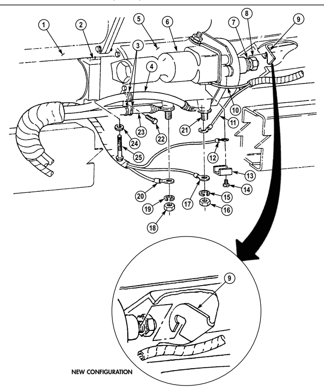
a. Removal 1. Remove nut (18), lockwasher (19), lead 3D (20), and negative cable 7A (23) from starter (5). Discard lockwasher (19).
- Remove adhesive sealant from positive terminal (21) on starter (5).
NOTE 4-16 Change 3
-
Perform step 3 for all vehicles except M1123 and "A2" series vehicles.
-
Perform step 4 for M1123 and "A2" series vehicles only.
-
Remove nut (16), lockwasher (15), leads 81A (11) and 81B (17), and positive cable 6A (4) from starter (5). Discard lockwasher (15) and tiedown strap (9.1).
-
Remove nut (16), lockwasher (15), and lead 81B (17) from starter (5). Discard lockwasher (15). 5. Remove screw (14), clip (13), and leads 74B (12) and 74A (10) from solenoid (6). 6. Remove screw (22), two clamps (3), negative cable 7A (23), and positive cable 6A (4) from starter (5).
-
Loosen plain-assembled nut (8) and washer (7) (if installed) on stud connecting starter (5) to bracket (9). Discard plain-assembled nut (8).
-
While supporting starter (5) from under vehicle, remove two capscrews (25) and washers (24) from starter (5) and engine (1).
-
Remove starter (5) and shim (2) from engine (1).
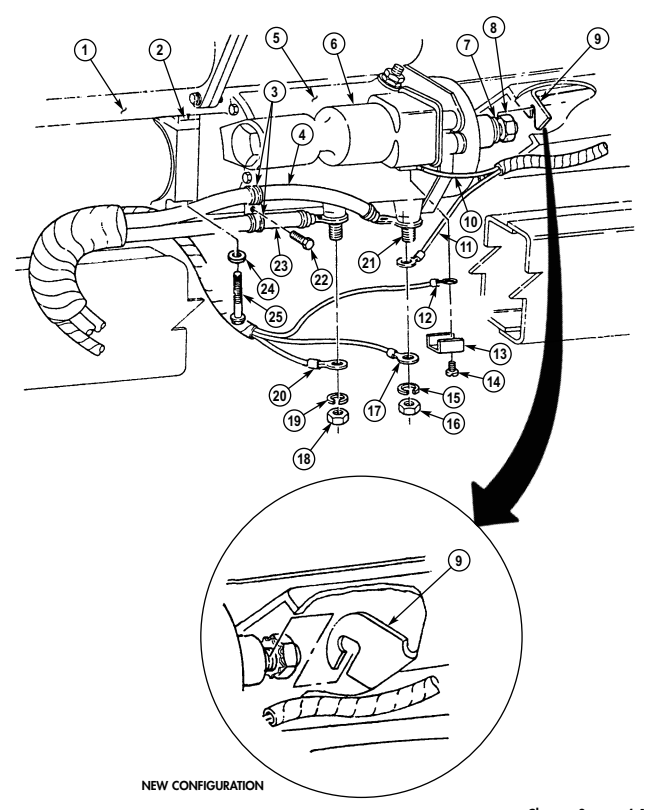
b. Installation 1. Install an 0.08 in. (2 mm) shim (2) on starter (5). 2. Position shim (2) and starter (5) to flywheel housing with solenoid (6) facing outward. 3. Slide front stud on starter (5) in bracket (9).
Some capscrews have sealing compound pre-applied. Additional sealing compound is not required.
-
Apply sealing compound to capscrews (25). Install two washers (24) and capscrews (25) on starter (5) and engine (1). Tighten capscrews (25) to 30-40 lb-ft (41-54 N•m).
-
Secure starter (5) on bracket (9) with plain-assembled nut (8). Using crowfoot, tighten plain-assembled nut (8) to 15-19 lb-ft (20-26 N•m).
-
Install two clamps (3), and negative cable 7A (23) and positive cable 6A (4), on starter (5) with screw (22).
-
Connect leads 74A (10) and 74B (12) to solenoid (6) with clip (13) and screw (14). Tighten screw (14) to 20 lb-in. (2 N•m).
Perform step 8 for all vehicles except M1123 and "A2" series vehicles. Perform step 9 for M1123 and "A2" series vehicles only.
- Connect positive cable 6A (4) and leads 81A (11) and 81B (17) to starter (5) with lockwasher (15) and nut (16). Using torque adapter, tighten nut (16) to 25-30 lb-ft (34-41 N•m).
8.1. Deleted.
-
Connect lead 81B (17) to starter (5) with lockwasher (15) and nut (16). Tighten nut (16) to 25-30 lb-ft (34-41 N•m).
-
Seal positive terminal (21), leads 81B (17) and 81A (11), and positive cable 6A (4) with adhesive sealant. Apply sealant at least 1.8 in. (3.175 mm) thick, covering all exposed metal attached to the positive terminal (21).
-
Connect negative cable 7A (23) and lead 3D (20) to starter (5) with lockwasher (19) and nut (18). Using torque adapter, tighten nut (18) to 15-20 lb-ft (20-27 N•m).
4-8. Starter Replacement (Cont'D)
FOLLOW-ON TASKS: - Install converter housing cover (para. 5-19).
- Install sealed upper converter housing cover (para. 5-18). - Connect battery ground cable (para. 4-73). - Install arctic heater oil pan shroud (para. 12-48.2). - Start engine (TM 9-2320-280-10) and check for smooth starter engagement.
4-9. Circuit Breaker Replacement
This task covers: INITIAL SETUP: Tools General mechanic's tool kit: automotive (Appendix B, Item 1)
a. Removal b. Installation
Manual References TM 9-2320-280-10 TM 9-2320-280-24P Materials/Parts Two lockwashers (Appendix G, Item 136) Equipment Condition Battery ground cable disconnected (para. 4-73).
- All circuit breakers are removed and installed basically the same. - This procedure covers the instrument gauge circuit breaker. - Prior to removal, tag leads for installation.
A. Removal
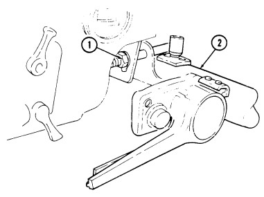
- Loosen nut (1) and lower steering column (2). 2. Disconnect lead 29B (8) and 29D (9) from circuit breaker (6). 3. Remove two nuts (4), lockwashers (5), screws (7), and circuit breaker (6) from column bracket (3).
Discard lockwasher (5).
B. Installation
-
Install circuit breaker (6) on column bracket (3) with two screws (7), lockwashers (5) and nuts (4).
-
Connect leads 29B (8) and 29D (9) to circuit breaker (6). 3. Raise steering column (2) and tighten nut (1) to 31 lb-ft (42 N•m).
4-9. Circuit Breaker Replacement (Cont'D)
FOLLOW-ON TASKS: - Connect battery ground cable (para. 4-73).
· Check operation of circuit breaker (TM 9-2320-280-10).
Section Iii. Instruments, Sending Units, Switches, And Horn Maintenance
4-10. INSTRUMENTS, SENDING UNITS, SWITCHES, AND HORN MAINTENANCE TASK
SUMMARY
| Tools | Personnel Required |
|---|---|
| General mechanic's tool kit: One mechanic | |
| automotive (Appendix B, Item 1) One assistant | |
| Materials/Parts Manual References | |
| Two lockwashers (Appendix G, Item 138) TM 9-2320-280-24P | |
| Lockwasher (Appendix G, Item 148) Equipment Condition | |
| Lockwasher (Appendix G, Item 150) - Batteries removed (para. 4-79). Sealing compound (Appendix C, Item 47.1) | |
| - Fixed rear door removed (para. 10-14). | |
| a. Removal | |
| NOTE | |
| Prior to removal, tag leads for installation. | |
| 1. | Remove nut (5), lockwasher (4), washer (3), and positive power cable (2) from buss bar (1). Discard |
| lockwasher (4). | |
| 2. | Remove capscrew (6), lockwasher (7), negative power cable (8), and two cables (9) from shunt (10). |
| Discard lockwasher (7). | |
| 3. | Remove five capscrews (20), two lockwashers (19), washers (18), and coverplate (17) from "B" beam (12). |
| Discard lockwashers (19). | |
| 4. | Remove two nuts (15), washers (14), capscrews (25), washers (26), and mounting bracket (27) from |
| coverplate (17). | |
| 5. | Remove nut (28), screw (23), and cover chain (21) from mounting bracket (27). |
| 6. | Remove cover (22) with cover chain (21) from umbilical power cable assembly (29). |
| 7. | Remove four nuts (30), screws (24), and mounting bracket (27) from umbilical power cable assembly (29). |
| 8. | Pull umbilical power cable assembly (29) through grommet (11) and coverplate (17), and remove |
| from vehicle (16). | |
| 9. | Remove grommet (11) from battery box (13). |
| b. Installation | |
| 1. | Install grommet (11) on battery box (13). |
| 2. | Route umbilical power cable assembly (29) through coverplate (17) and grommet (11), and position |
| in approximate mounting location on vehicle (16). | |
| 3. | Install cover chain (21) on mounting bracket (27) with screw (23) and nut (28). |
| 4. | Install umbilical power cable assembly (29) on mounting bracket (27) with four screws (24) and |
| nuts (30). | |
| 5. | Install cover (22) on umbilical power cable assembly (29). |
| 6. | Install coverplate (17) on "B" beam (12) with two washers (18), lockwashers (19), and five |
| capscrews (20). | |
| 7. | Install mounting bracket (27) on coverplate (17) with two washers (26), capscrews (25), washers (14), |
| and nuts (15). | |
| 8. | Install two cables (9) and negative power cable (8) on shunt (10) with lockwasher (7) and |
| capscrew (6). | |
| 9. | Install positive power cable (2) on buss bar (1) with washer (3), lockwasher (4), and nut (5). |
| 10. | Apply silicone compound to cable (2), coating all exposed metallic surfaces. |
4-11. Instrument Cluster Replacement
This task covers: INITIAL SETUP:
Tools
General mechanic's tool kit: automotive (Appendix B, Item 1) Materials/Parts Five lockwashers (Appendix G, Item 169) Antiseize compound (Appendix C, Item 13)
A. Removal B. Installation
Manual References TM 9-2320-280-10 TM 9-2320-280-24P Equipment Condition Battery ground cable disconnected (para. 4-73).
NOTE Prior to removal, tag leads for installation.
A. Removal
-
Remove four capscrews (6) from instrument cluster (7) and instrument panel (3). Pull instrument cluster (7) away from instrument panel (3) to allow access to speedometer cable (4).
-
Loosen nut (5) and disconnect speedometer cable (4) from speedometer (1). 3. Disconnect harness lead 27J (8), 28A (9), 40B (13), 27H (14), 36A (15), 57L (19), 17B (20), 27G (21), 33A (22), 40C (17), and 567A (18) from instrument cluster (7).
-
Remove four nuts (12), lockwashers (11), and harness ground leads 58H (10), 58G (25), 58E (23), and 58F (24) from instrument cluster (7). Discard lockwashers (11).
-
Remove screw (12.1), lockwasher (11.1), and ground lead 57G (16) from instrument cluster (7) and
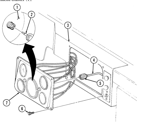
remove instrument cluster (7).
4-11. Instrument Cluster Replacement (Cont'D)
b. Installation 1. Apply antiseize compound to harness ground leads 58H (10), 58G (25), 58E (23), and 58F (24) and install on instrument cluster (7) with five lockwashers (11) and nuts (12).
-
Apply antiseize compound to harness ground lead 57G (16) and install on instrument cluster (7) with lockwasher (11.1) and screw (12.1).
-
Connect harness leads 27J (8), 28A (9), 40B (13), 27H (14), 36A (15) 57L (19), 17B (20), 27G (21), 33A (22), 40C (17), and 567A (18) to instrument cluster (7).
-
Connect speedometer cable (4) to speedometer (1) ensuring core (2) engages with square hole in speedometer (1) and secure with nut (5).
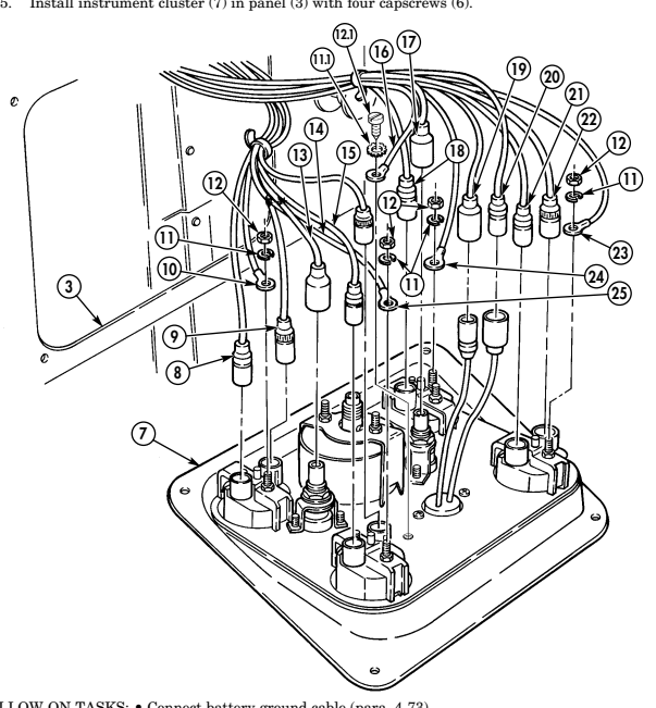
FOLLOW-ON TASKS: - Connect battery ground cable (para. 4-73).
- Check operation of instrument cluster components (TM 9-2320-280-10).
4-12. Instrument Panel Replacement
This task covers: INITIAL SETUP: Tools Equipment Condition General mechanic's tool kit: Instrument cluster removed (para. 4-11).
automotive (Appendix B, Item 1) Heater control cables remove (para. 10-89).
Manual References TM 9-2320-280-10 TM 9-2320-280-24P
A. Removal B. Installation Note
Prior to removal, tag leads for installation.
Loosen nut (9) and lower steering column (3).
Remove cannon plug (11) from main light switch (10).
Remove two capscrews (12), washers (13), nuts (14), and washers (13) from instrument panel (2) and body (1).
Remove nut (16) and screw (17) from hand throttle bracket (15) and instrument panel (2). Remove nut (4), washer (5), capscrew (7), washer (5) and hand throttle bracket (15) from steering column bracket (8) and instrument panel (2). Remove screw (6) from instrument panel (2) and body (1).
Pull instrument panel (2) away from body (1). Disconnect two harness leads 11A (28), 14A (29), and 27A (27) from rotary switch (26).
Disconnect two harness leads 27F (32) and 571A (31) at wait-to-start indicator light (24). Disconnect two harness leads 27L (30) and 67D (33) at brake warning indicator light (22). Disconnect harness lead 400 D (18) from resistor (21). Disconnect harness lead 27E (19) from blower switch (20) and remove instrument panel (2). Disconnect hose (25) from air restriction gage (23).
B. Installation
Connect hose (25) to air restriction gage (23). Connect harness lead 27E (19) to blower switch (20). Connect harness lead 400D (18) to resistor (21).
Connect two harness leads 27L (30) and 67D (33) to brake warning indicator light (22). Connect two harness leads 27F (32) and 571A (31) to wait-to -start indicator light (24). Connect three harness leads 11A (28), 14A (29), and 27A (27) to rotary switch (26).
Install instrument panel (2) on body (1) with screw (6).
Install instrument panel (2) and hand throttle bracket (15) to steering column bracket (8) with washer (5), capscrew (7), washer (5), and nut (4). Install hand throttle bracket (15) to instrument panel (2) with screw (17) and nut (16).
Install instrument panel (2) to body (1) with two washers (13), capscrews (12), and washers (13), and nuts (14).
Install cannon plug (11) to main light switch (10). Raise steering column (3) and tighten nut (9) to 31 lb-ft (42 N*m).
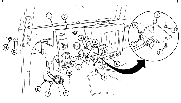
4-12. Instrument Panel Replacement (Cont'D)
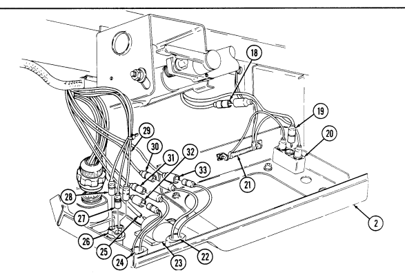
FOLLOW-ON TASKS: - Install heater cables (para. 10-89).
· Install instrument cluster (para. 4-11). · Check operation of instrument panel components (TM 9-2320-280-10).
4-13. Electrical Gauge Replacement
This task covers: INITIAL SETUP: Tools General mechanic's tool kit: automotive (Appendix B, Item 1)
a. Removal b. Installation
| Manual References |
|---|
| TM 9-2320-280-10 |
TM 9-2320-280-10 TM 9-2320-280-24P Materials/Parts Two lockwashers (Appendix G, Item 169) Equipment Condition Battery ground cable disconnected (para. 4-73).
-
All electrical gauges are removed and installed basically the same. This procedure covers the temperature gauge.
-
Prior to removal, tag all leads for installation.
a. Removal 1. Remove four capscrews (8) from instrument cluster (1) and instrument panel (6). 2. Pull instrument cluster (1) away from panel (6). 3. Disconnect leads (4) and (5) from gauge (9). 4. Remove two nuts (3), lockwashers (7), gauge retaining bracket (2), and gauge (9) from instrument cluster (1). Discard lockwashers (7).
B. Installation
-
Install gauge (9) and retaining bracket (2) on instrument cluster (1) with two new lockwashers (7) and nuts (3). Tighten nuts (3) to 8 lb-in. (1 N•m).
-
Connect leads (4) and (5) to gauge (9). 3. Install instrument cluster (1) to panel (6) with four capscrews (8).
4-13. Electrical Gauge Replacement (Cont'D)
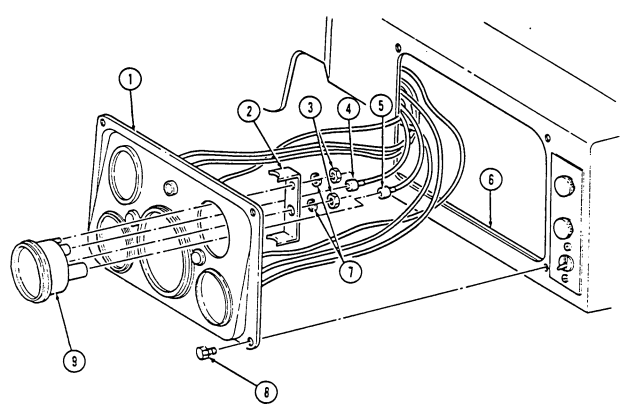
FOLLOW-ON TASKS: - Connect battery ground cable (para. 4-73).
· Start engine and check operation of gauge (TM 9-2320-280-10).
4-13.1. Tachometer Replacement
This task covers:
| TASK | PAGE | |
|---|---|---|
| PARA. | PROCEDURES | NO. |
| 4-7. | Rotary Switch Replacement | 4-14 |
| 4-8. | Starter Replacement | 4-16 |
| 4-9. | Circuit Breaker Replacement | 4-20 |
| 4-7. | ROTARY SWITCH REPLACEMENT |
Seal (Appendix G, Item 285) Two lockwashers (Appendix G, Item 138) Lockwasher (Appendix G, Item 168)
A. Removal
-
Remove engine harness connector (2) from tachometer connector (1). 2. Remove seven screws (4), lockwashers (3), washers (25), cover (5), and gasket (24) from tach/hourmeter box (18). Discard lockwashers (3) and gasket (24).
-
Remove nut (33), lockwasher (34), ground cable (32), and washer (35) from stud (27).
Discard lockwasher (34).
-
Remove locknut (36), washer (31), and safety lanyard (30) from stud (28). Discard locknut (36). 5. Remove locknut (37), washer (38), and washer (39) from stud (26) and remove tach/hourmeter box (18) from engine access cover (29). Discard locknut (37).
-
Remove seal (40) from tach/hourmeter box (18). Discard seal (40). 7. Remove nut (15), washer (14), washer (6), and screw (7) from tach/hourmeter box (18). 8. Remove two nuts (21), lockwashers (22), and bracket (19) from tach/hourmeter box (18).
Discard lockwashers (22).
-
Remove nuts (13) and (17) from cable connectors (8) and (23).
-
Remove nut (10), lockwasher (11), washer (12), toggle switch (9), cable connectors (8) and (23), and tachometer (16) from tach/hourmeter box (18) Discard lockwasher (11).
B. Installation
-
Install cable connectors (8) and (23) to tach/hourmeter box (18) with nuts (13) and (17). 2. Install toggle switch (9) in tach/hourmeter box (18) with washer (12), lockwasher (11), and nut (10). 3. Install tachometer (16) to tach/hourmeter box (18) with bracket (19), two lockwashers (22), and nuts (21).
-
Install screw (7), washer (6), washer (14), and nut (15) on tach/hourmeter box (18). 5. Install seal (40) on tach/hourmeter box (18). 6. Install tach/hourmeter box (18) on engine access cover (29) with washer (39), washer (38), and locknut (37).
-
Install safety lanyard (30) to stud (28) with washer (31) and locknut (36).
4-13.1. Tachometer Replacement (Cont'D)
-
Install ground cable (32) to stud (27) with washer (35), lockwasher (34), and nut (33). 9. Install cover (5) and gasket (24) to tach/hourmeter box (18) with seven washers (25), lockwashers (3), and screws (4).
-
Install engine harness plug (2) to tachometer connector (1).
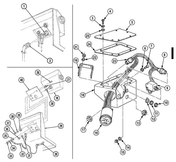
FOLLOW-ON TASKS: - Install engine access cover (para. 10-15).
- Install radio rack (para. 12-132). - Install radio rack mounting brackets (para. 12-130). - Connect battery ground cables (para. 4-73).
4 - 1 3 . 2 . Tachometer Cable Connector Assembly Replacement
This task covers:
| a. Removal | b. Installation |
|---|---|
| INITIAL SETUP: | |
| Tools | Manual References |
| General mechanic's tool kit: | TM 9-2320-280-10 |
| automotive (Appendix B, Item 1) | TM 9-2320-280-24P |
| Materials/Parts | Equipment Condition |
| Two lockwashers (Appendix G, Item 136) |
a. Removal 1. Remove screw (13), washer (14), and cable connector wire lead 12 (15) from terminal post SIG (3) on tachometer (1).
-
Remove screw (8), washer (7), and cable connector wire lead 13 (6) from terminal post SIG (4) on tachometer (1).
-
Remove screw (12), washer (11), and cable connector leads 58A (9) and 58B (10) from terminal post NEG (5) on tachometer (1).
-
Remove screw (16) ,washer (17), and cable connector wire leads 458A (35) and 458B (36) from terminal post POS (2) on tachometer (1).
-
Remove screw (23), washer (24), and cable connector wire lead 11 (25) from terminal post 5 (28) on toggle switch (29).
-
Remove screw (34), washer (33), and cable connector wire lead 10 (32) from terminal post 2 (30) on toggle switch (29).
B. Installation
-
Install cable connector wire lead 10 (32) to terminal post 2 (30) on toggle switch (29) with washer (33) and screw (34).
-
Install cable connector wire lead 11 (25) to terminal post 5 (28) on toggle switch (29) with washer (24) and screw (23).
-
Apply approximately 0.125-in. of adhesive sealant to wire leads 13 (6), 58A (9), 58B (10), 12 (15), 458A (35), 458B (36) and terminal posts POS (2), SIG (3), SIG (4), and NEG (5).
-
Install cable connector wire leads 458A (35) and 458B (36) to terminal post POS (2) on tachometer (1) with washer (17) and screw (16).
-
Remove screw (21), washer (22), and cable connector wire lead 97A (26) from terminal post 4 (27) on toggle switch (29).
-
Remove screw (18), washer (19), and cable connector lead 97B (20) from terminal post 1 (31) on toggle switch (29).
-
Apply approximately 0.125 in. (3.175 mm) adhesive sealant to wire leads 97A (26), 97B (20), 10 (32), 11 (25) and terminal posts 1 (31), 2 (30), 4 (27), and 5 (28).
-
Install cable connector wire lead 97B (20) to terminal post 1 (31) on toggle switch (29) with washer (19) and screw (18).
-
Install cable connector wire lead 97A (26) to terminal post 4 (27) on toggle switch (29) with washer (22) and screw (21).
4-13.2. Tachometer Cable Connector Assembly Replacement (@Tr'D)
Install cable connector wire leads 58A (9) and 58B (10) to terminal post NEG (5) on tachometer (1) with washer (11) and screw (12).
Install cable connector wire lead 13 (6) to terminal post SIG (4) on tachometer (1) with washer (7) and screw (8).
Install cable connector wire lead 12 (15) to terminal post SIG (3) on tachometer (1) with washer (14) and screw (13).
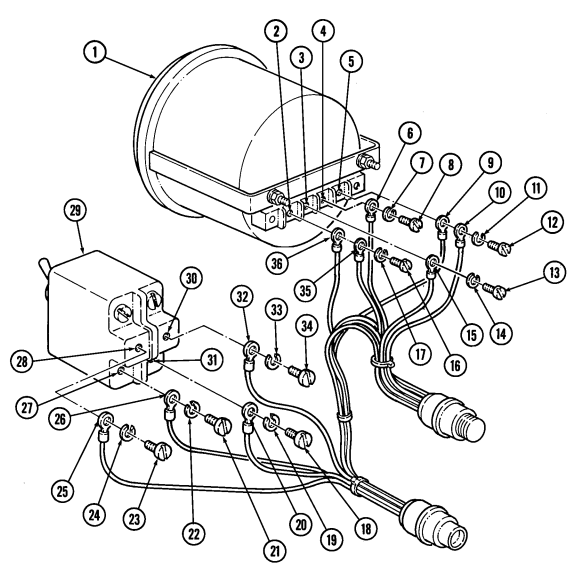
FOLLOW-ON TASK: Install tachometer (para. 4-13.1).
| SUMMARY |
|---|
4 - 1 4 . Speedometer/Odometer Replacement
A. Removal
- Remove four capscrews (9) from instrument cluster (4) and instrument panel (8). 2. Pull instrument cluster (4) away from panel (8). 3. Loosen large nut (2) on speedometer cable (7) and pull cable end out of speedometer (3). 4. Remove two nuts (6), speedometer retaining bracket (5), and speedometer (3) from instrument cluster (4).
B. Installation
-
Install speedometer (3) and speedometer retaining bracket (5) on instrument cluster (4) with two nuts (6). Tighten nuts (6) to 8 lb-in. (1 N•m).
-
Install speedometer cable (7) into back of speedometer (3), ensuring core (1) engages in square hole in speedometer (3), and tighten cable nut (2).
-
Install instrument cluster (4) to panel (8) with four capscrews (9).
4-14. Speedometer/Odometer Replacement (Cont'D)
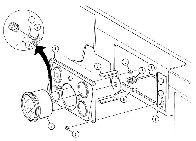
FOLLOW-ON TASK: Check operation of speedometer (TM9-2320-280-10).
4-15. Speedometer Cable And Core (12338428) Replacement
This task covers:
| INITIAL SETUP: |
|---|
| Tools | Manual References |
|---|---|
| General mechanic's tool kit: | TM 9-2320-280-10 |
| automotive (Appendix B, Item 1) | TM 9-2320-280-24P |
| Materials/Parts | Equipment Condition |
| Two lockwashers (Appendix G, Item 169) | Battery ground cable disconnected (para. 4-73). |
a. Removal b. Installation
a. Removal
If vehicle is equipped with speedometer cable (12338428-2), refer to para. 4-15.1.
-
Remove four capscrews (12) from instrument cluster (11) and instrument panel (10) and pull instrument cluster (11) away to gain access to back of speedometer (3).
-
Remove speedometer driveshaft nut (2) from speedometer (3). 3. Push speedometer cable (5) and rubber grommet (4) through body (8). 4. Remove screw (9) and plain-assembled nut (6) from clamp (7) on body (8). Remove clamp (7) from speedometer cable (5). Discard plain-assembled nut (6).
-
Working under vehicle, remove screw (14) and clamp (13) from side of transmission (15). Remove clamp (13) from speedometer cable (5).
-
Remove speedometer driveshaft nut (18) and speedometer cable (5) from adapter (16) on transfer case (17) and remove speedometer cable (5).
B. Installation
-
Install speedometer cable (5) into adapter (16), ensuring core (1) engages in square hole in adapter (16), and tighten speedometer cable nut (18).
-
Install speedometer cable (5) and clamp (13) on side of transmission (15) with screw (14). 3. Secure speedometer cable (5) and clamp (7) on body (8) with screw (9) and plain-assembled nut (6). 4. Install speedometer cable (5) and grommet (4) on body (8). 5. Install speedometer cable (5) into back of speedometer (3), ensuring core (1) engages in square hole in speedometer (3) and tighten speedometer cable nut (2).
-
Install instrument cluster (11) on panel (10) with four capscrews (12).
4-15. Speedometer Cable And Core (12338428) Replacement (Cont'D)
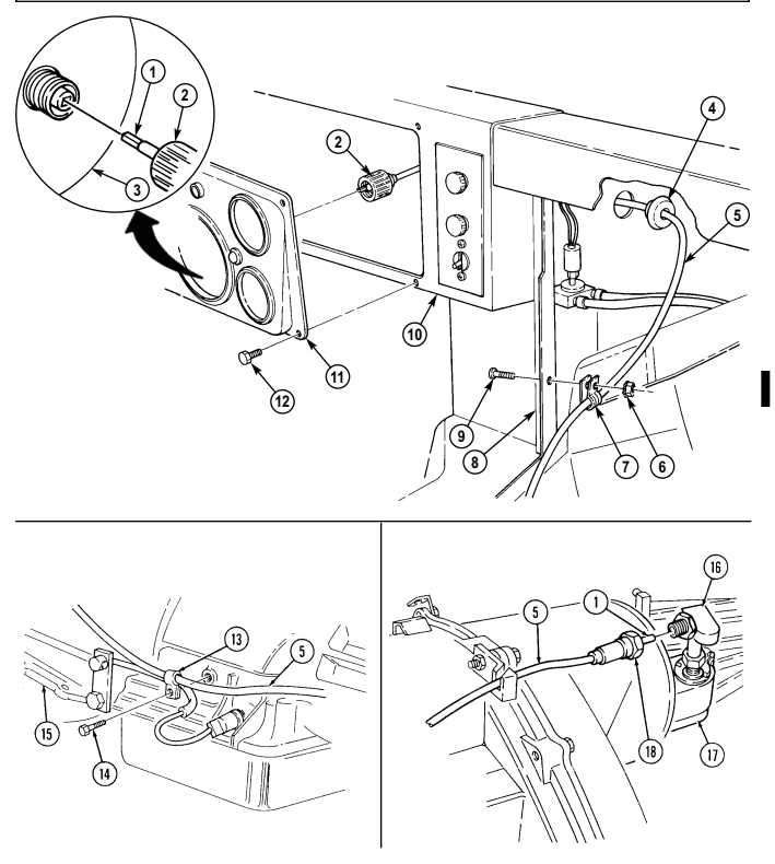
FOLLOW-ON TASKS: - Lower and secure hood (TM 9-2320-280-10).
· Install engine access cover (para. 10-15).
4-15.1. Speedometer Cable And Core (12338428-2) Replacement
| INITIAL SETUP: | |
|---|---|
| Applicable Models | Manual References |
| M1123 | TM 9-2320-280-24P |
| Tools | Equipment Condition |
| General mechanic's tool kit: | - Battery ground cable disconnected |
| automotive (Appendix B, Item 1) | (para. 4-73). |
| Material/Parts | - Radio rack removed (para. 12-132). |
| - Radio rack mounting brackets removed | |
| Gasket (Appendix G, Item 55) | (para. 12-130). |
| Seven lockwashers (Appendix G, Item 156) | - Engine access cover removed (para. 10-15). |
| Lockwasher (Appendix G. Item 155) |
| This task covers: |
|---|
a. Removal b. Installation
Tiedown strap (Appendix G, Item 315)
If vehicle is equipped with speedometer cable (12338428), refer to para. 4-15.
A. Removal
-
Remove tiedown strap (4) from speedometer cable (1) and wiring harness (3) behind instrument panel (2). Discard tiedown strap (4).
-
Remove four capscrews (11) and pull instrument cluster (10) away to gain access to back of speedometer (12).
-
Loosen nut (5) and remove speedometer cable (1) from speedometer (12). 4. Remove plain-assembled nut (7), clamp (6), screw (9), and speedometer cable (1) from body (8).
Discard plain-assembled nut (7).
-
Push speedometer cable (1) and grommet (13) through cowl (14). 6. Remove two nuts (18), screws (24), clamps (19), and speedometer cable (1) from two speedometer cable support braces (20) located in front of solenoid control valve (16) and behind alternator (15).
-
Remove nut (23), screw (21), and speedometer cable support brace (20) from two clamps (22) on hydraulic hoses (17) located in front of solenoid control valve (16).
-
Remove nut (23), screw (21), and speedometer cable support brace (20) from two clamps (22) on hydraulic hoses (17) located behind alternator (15).
-
Remove speedometer cable (1) from under alternator (15).
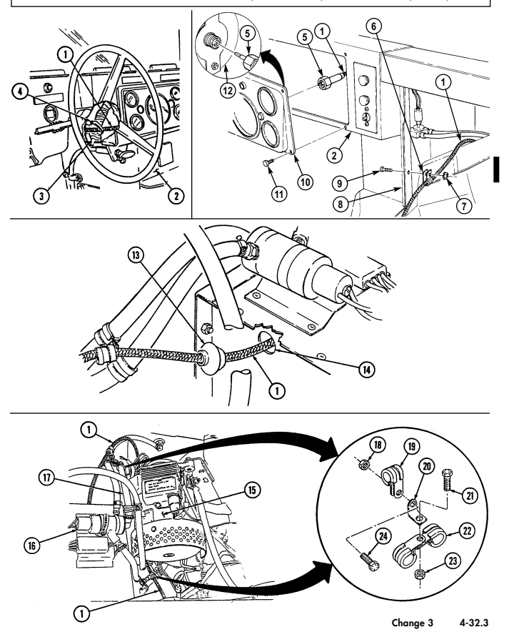
4-15.1. SPEEDOMETER CABLE AND CORE (12338428-2) REPLACEMENT (Cont'd)
4-15.1. Speedometer Cable And Core (12338428-2) Replacement (Cont'D)
- Remove screw (4), clamp (1), and speedometer cable (2) from transmission (3). 11. Remove speedometer cable (2) from standoff bracket (8) on transfer case (6). 12. Loosen nut (7) and remove speedometer cable (2) from adapter (5) on transfer case (6).
b. Installation 1. Install speedometer cable (2) into adapter (5) on transfer case (6) and tighten nut (7) to 90-110 lb-in (10-12 Nom).
- Install speedometer cable (2) through standoff bracket (8) on transfer case (6).
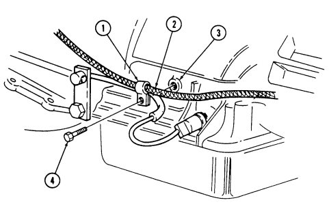 3. Install speedometer cable (2) on transmission (3) with clamp (1) and screw (4).
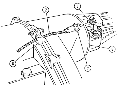
4-15.1. Speedometer Cable And Core (12338428-2) Replacement (Cont'D)
NOTE If installing speedometer cable (12338428-2) for the first time, perform steps 4 and 5. If not go to step 6.
- Install plug (9) in existing hole (10) located in left inner cowl (11).
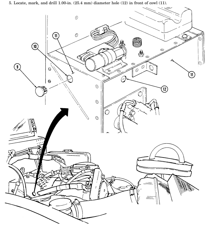
4-15.1. Speedometer Cable And Core (12338428-2) Replacement (Cont'D)
-
Install speedometer cable (4) on body (6) with clamp (3), screw (7), and plain-assembled nut (5).
-
Route speedometer cable (4) under alternator (11) next to hydraulic hoses (13). 8. Install speedometer cable support brace (16) on two clamps (18) and hydraulic hoses (13) located behind alternator (11) with screw (17) and nut (19).
-
Install speedometer cable (4) and clamp (15) on speedometer cable support brace (16) with screw (20) and nut (14).
-
Install speedometer cable support brace (16) on two clamps (18) and hydraulic hoses (13) located in front of solenoid control valve (12) with screw (17) and nut (19).
-
Install speedometer cable (4) and clamp (15) on speedometer cable support brace (16) with screw (20) and nut (14).
-
Install speedometer cable (4) and grommet (21) into cowl (22). 13. Install speedometer cable (4) on speedometer (1). 14. Install instrument cluster (9) on instrument panel (8) with four capscrews (10). 15. Install tiedown strap (24) on speedometer cable (4) and wiring harness (23) behind instrument
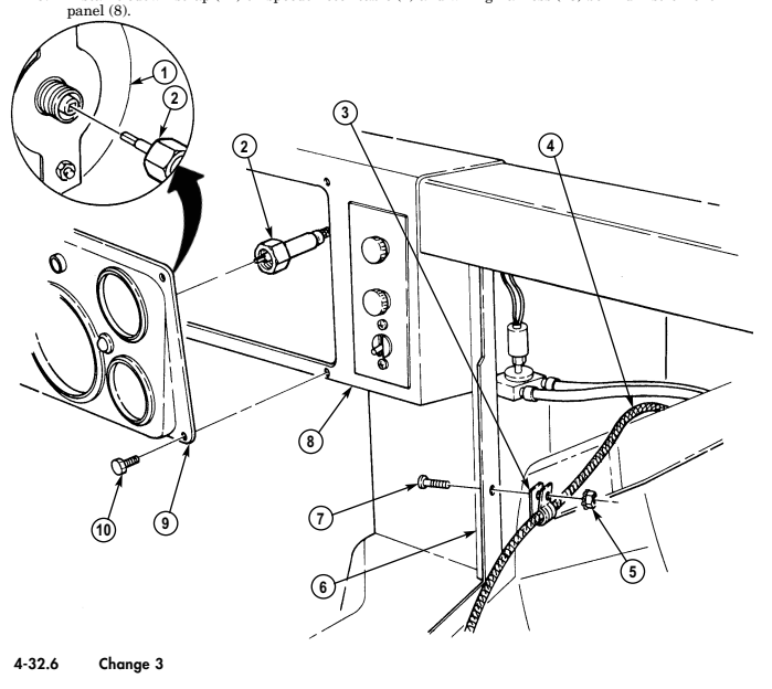
4-15.1. SPEEDOMETER CABLE AND CORE (12338428-2) REPLACEMENT (Cont'd)
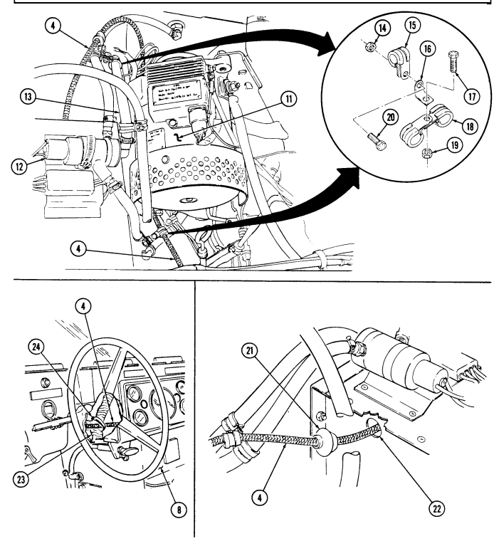
FOLLOW-ON-TASK: - ● Install left splash shield (para. 10-17).
· Connect battery ground cable (para. 4-73).
· Install fuel filler drain hose (para 3-34).
· Install engine access cover (para. 10-15).
· Lower and secure hood (TM 9-2320-280-10).
4-16. Instrument Cluster Light Replacement
This task covers: INITIAL SETUP: automotive (Appendix B, Item 1) Manual References TM 9-2320-280-10 TM 9-2320-280-24P
A. Lamp Removal
-
Remove light lens (1) and gasket (2) from light assembly (4).
-
Remove lamp (3) from light assembly (4).
B. Lamp Installation
- Install lamp (3) into light assembly (4).
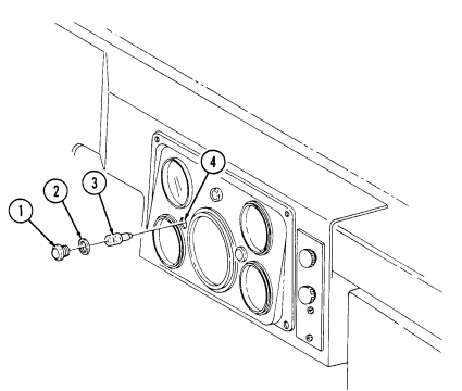 2. Install gasket (2) and lens (1) to light assembly (4).
a. Lamp Removal c. Light Assembly Removal b. Lamp Installation d. Light Assembly Installation Tools Equipment Condition General mechanic's tool kit: Battery ground cable disconnected (para. 4-73).
4-16. Instrument Cluster Light Replacement (Cont'D)
C. Light Assembly Removal
-
Remove two light lenses (1) and gaskets (2) from light assemblies (4).
-
Remove lamp (3) from light assembly (4) being replaced. 3. Remove all electrical gauges (para. 4-13) and speedometer/odometer (para. 4-14). 4. Separate instrument cluster (8) from backing panel (6). 5. Disconnect harness lead 40B (5) from light assembly (4). 6. Remove two screws (7) and light assembly (4) from backing panel (6).
D. Light Assembly Installation
Install light assembly (4) to backing panel (6) with two screws (7). Install backing panel (6) to instrument cluster (8).
Install all electrical gauges (para. 4-13) and speedometer/odometer (para. 4-14). Connect harness lead 40B (5) to light assembly (4).
Install lamp (3) into light assembly (4).
Install two gaskets (2) and light lenses (1) on light assemblies (4).
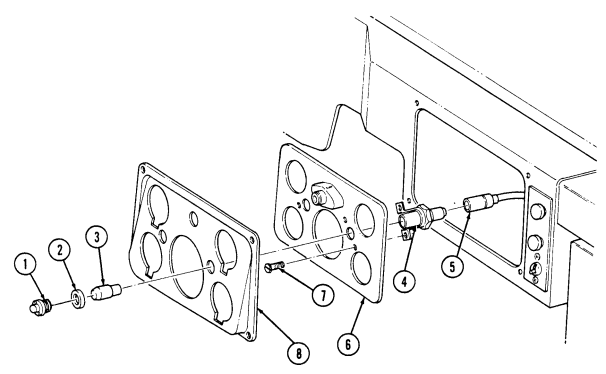
FOLLOW-ON TASK: Connect battery ground cable (para. 4-73).
4-17. Wait-TO-Start Lamp Replacement
This task covers:
A. Removal B. Installation
INITIAL SETUP: Tools General mechanic's tool kit: automotive (Appendix B, Item 1) Maintenance and repair shop equipment: automotive (Appendix B, Item 2) Manual References TM 9-2320-280-10 TM 9-2320-280-24P
Equipment Condition
- Battery ground cable disconnected (para. 4-73). - Instrument cluster removed (para. 4-11).
Note
Prior to removal, tag leads and note position for installation.
A. Removal
-
Loosen nut (14) and lower steering column (7). 2. Remove cannon plug (16) from main light switch (15). 3. Remove two capscrews (17), washers (18), nuts (20), and washers (18) from instrument panel (6) and body (19).
-
Remove nut (22) and screw (23) from hand throttle bracket (21) and instrument panel (6). 5. Remove nut (13), washer (11), capscrew (10), and washer (11) from instrument panel (6), hand throttle bracket (21), and steering column bracket (12).
-
Remove screw (8) from instrument panel (6) and cowl (9). 7. Pull instrument panel (6) away from body (19). 8. Remove two screws (5) from wait-to-start lamp (4) and instrument panel (6). 9. Disconnect lead 571 (2) and 27 (3) from wiring harness (1).
-
Remove wait-to-start lamp (4).
B. Installation
-
Connect lead 571 (2) and 27 (3) to wiring harness (1). 2. Install wait-to-start lamp (4) on instrument panel (6) with two screws (5). 3. Install instrument panel (6) on cowl (9) with screw (8). 4. Install instrument panel (6) and hand throttle bracket (21) on steering column bracket (12) with capscrew (10), washer (11), nut (13), and washer (11).
-
Install hand throttle bracket (21) to instrument panel (6) with screw (23) and nut (22). 6. Install instrument panel (6) to body (19) with two capscrews (17), washers (18), nuts (20), and washers (18).
-
Install cannon plug (16) on main light switch (15). 8. Raise steering column (7) and tighten nut (14) to 31 lb-ft (42 N•m).
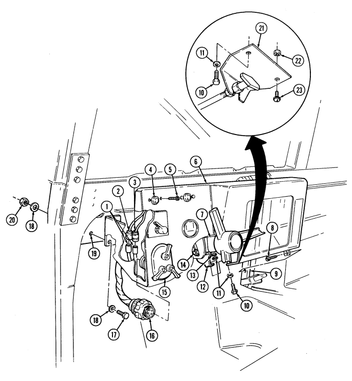
FOLLOW-ON TASKS: - Install instrument cluster (para. 4-11).
-
Connect battery ground cable (para. 4-73).
-
Start engine (TM 9-2320-280-10) and check wait-to-start lamp assembly for operation.
4-17.1 Brake Warning Lamp Replacement
This task covers: INITIAL SETUP: Tools General mechanic's tool kit: automotive (Appendix B, Item 1) Materials/Parts Tape (Appendix C, Item 50) a. Removal b. Installation Manual References TM 9-2320-280-10 TM 9-2320-280-24P Equipment Condition
- Battery ground cables disconnected (para. 4-73). - Air restriction gauge removed (para. 3-17).
Prior to removal, tag leads for installation.
a. Removal 1. Remove two screws (2) from brake warning lamp (1) and instrument panel (5). 2. Disconnect leads 67 (7) and 27 (3) from wiring harness leads (6). 3. Slide brake warning lamp (1) down toward steering column (4) and remove brake warning lamp (1).
b. Installation
Place tape around lead wires to keep lamp in proper position during installation.
-
Install tape (8) around lamp (1) and lead wires (7) and (3). 2. Slide brake warning lamp (1) up along steering column (4) and install brake warning lamp (1) on instrument panel (5) with two screws (2).
-
Connect leads 67 (7) and 27 (3) to wiring harness leads (6).
4-17.1. Brake Warning Lamp Replacement (Gnt'D)
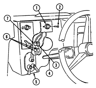
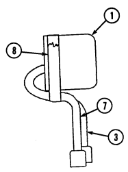
FOLLOW-ON TASKS: - Install air restriction gauge (para. 3-17).
- Connect battery ground cables (para. 4-73).
- Start engine (TM 9-2320-280-10) and check brake warning lamp for operation.
4-18. High Beam Lamp Replacement
This Task Covers: a. Removal b. Installation INITIAL SETUP: Tools General mechanic's tool kit: automotive (Appendix B, Item Equipment Condition Electrical gauges removed (para. 4-13).
Speedometer/odometer removed (para. 4-14).
Manual References TM 9-2320-280-24P
Prior to removal, tag leads for installation.
A. Removal
-
Remove two light lenses (7) from instrument cluster back panel (4).
-
Remove instrument cluster (6) from instrument cluster back panel (4).
-
Disconnect harness lead 57L (1) and lead 17B (2) from high beam lamp (5).
-
Remove two screws (3) and high beam lamp (5) from instrument cluster back panel (4).
B. Installation
-
Install high beam lamp (5) on instrument cluster back panel (4) with two screws (3).
-
Connect harness lead 57L (1) and lead 178 (2) to high beam lamp (5). 3. Install instrument cluster (6) on instrument cluster back panel (4).
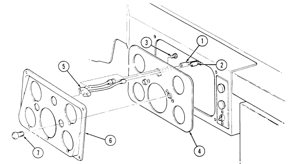 4. Install two light lenses (7) on instrument cluster back panel (4).
FOLLOW-ON TASKS: Install speedometer/odometer (para. 4-14).
Install electrical gauges (para. 4-13).
4-19. Parking Brake Switch Replacement
This Task Covers: a. Removal b. Installation INITIAL SETUP: automotive (Appendix B, Item 1) Tools Equipment Condition General mechanic's tool kit: Battery ground cable disconnected (para. 4-73).
Manual References TM 9-2320-280-24P
Prior to removal, tag leads for installation.
A. Removal
-
Disconnect parking brake switch lead 67C (1) and 67 (2) from wiring harness leads 67B (3) and 67E (4).
-
Remove parking brake switch (5) from parking brake lever (6).
b. Installation 1.
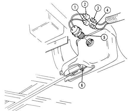
Install parking brake switch (5) to parking brake lever (6).
Connect lead 67C (1) and 67 (2) to wiring harness leads 67B (3) and 67E (4).
FOLLOW-ON TASKS: Connect battery ground cable (para. 4-73).
Check parking brake switch operation (TM 9-2320-280-10).
4-20. Horn Switch Replacement
| This task covers: | |
|---|---|
| a. Removal | b. Installation |
| INITIAL SETUP: | |
| Applicable Models | Material/Parts |
| M1123 | Sealant (Appendix C, Item 10) |
| Tools | Equipment Condition |
| General mechanic's tool kit: | Tachometer removed (para. 4-13.1). |
| automotive (Appendix B, Item 1) |
A. Removal
-
Remove snapring (5) from horn switch (4) and steering wheel (1).
-
Pull horn switch (4) out and disconnect from lead 25A (3) in steering shaft (2).
B. Installation
- Apply sealing compound to bushing (6).
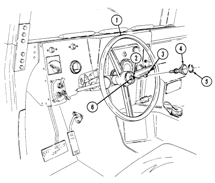 2. Connect lead 25A (3) to horn switch (4) and push into steering shaft (2). 3. Install snapring (5) on horn switch (4) and steering wheel (1).
FOLLOW-ON TASKS: Connect battery ground cable (para. 4-73).
Test horn for operation (TM 9-2320-280-10).
4-21. Horn Control Brush Replacement
This task covers:
| a. Removal | b. Installation |
|---|---|
| Tools | Manual References |
| General mechanic's tool kit: | TM 9-2320-280-10 |
| automotive (Appendix B, Item 1) | TM 9-2320-280-24P |
A. Lamp Removal
-
Loosen nut (1) and lower steering column (5). 2. Disconnect lead 25A (3) from horn control brush (4). 3. Remove two screws (2) from horn control brush (4) and steering column (5).
-
Pry horn control brush (4) out of steering column (5). 5. Clean sealant from steering column (5).
B. Installation
- Apply sealing to bottom of horn control brush (4).
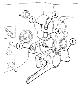
- Install horn control brush (4) into steering column (5) with two screws (2). 3. Connect lead 25A (3) to horn control brush (4). 4. Raise steering column (5) and tighten nut (1) to 31 lb-ft (42 Nom).
FOLLOW-ON TASKS: Connect battery ground cable (para. 4-73).
Check horn for proper operation (TM 9-2320-280-10).
4-22. Horn Replacement
This task covers: INITIAL SETUP: Tools General mechanic's tool kit: automotive (Appendix B, Item 1) Materials/Parts Two lockwashers (Appendix G, Item 175)
a. Removal b. Installation
Manual References TM 9-2320-280-10 TM 9-2320-280-24P Equipment Condition
- Battery ground cable disconnected (para. 4-73). - Hood raised and secured (TM 9-2320-280-10).
Prior to removal, tag leads for installation.
a. Removal 1. Remove two capscrews (4), lockwashers (5) and horn (2) from bracket (3). Discard lockwashers (5). 2. Disconnect lead 25A (1) and 26A (6) from horn (2).
b. Installation 1. Connect leads 25A (1) and 26A (6) to horn (2).
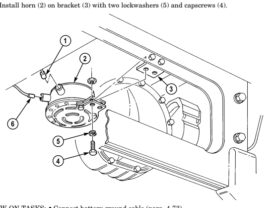
FOLLOW-ON TASKS: - Connect battery ground cable (para. 4-73).
- Lower and secure hood (TM 9-2320-280-10). - Check horn for proper operation (TM 9-2320-280-10).
4-23. Horn Mounting Bracket Replacement
This Task Covers:
| Applicable Models |
|---|
| All models except M1123 and "A2" series |
| vehicles |
| Tools |
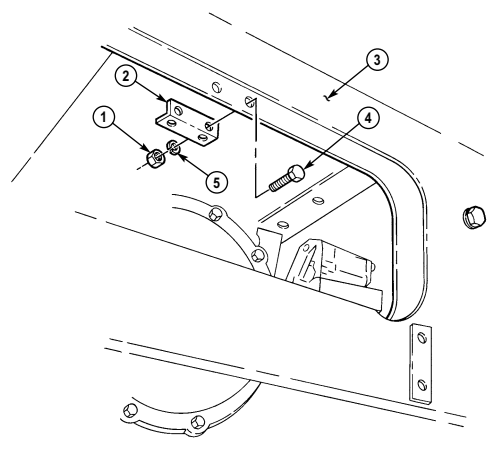
| Manual References |
|---|
| TM 9-2320-280-10 |
| TM 9-2320-280-24P |
| Equipment Condition |
Two lockwashers (Appendix G, Item 133)
a. Removal b. Installation
a. Removal Remove two nuts (1), lockwashers (5), capscrews (4) and horn mounting bracket (2) from front crossmember (3). Discard lockwashers (5).
b. Installation Install horn mounting bracket (2) on front crossmember (3) with two capscrews (4), lockwashers (5), and nuts (1). Tighten nuts (1) to 10 lb-ft (14 N•m).
FOLLOW-ON TASK: Install horn (para. 4-22).
4-24. Engine Temperature Sending Unit Replacement
This task covers:
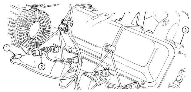
a. Removal b. Installation
| INITIAL SETUP: |
|---|
automotive (Appendix B, Item 1)
Materials/Parts Equipment Condition
Sealing compound (Appendix C, Item 44) Battery ground cable disconnected (para. 4-73).
Hood raised and secured (TM 9-2320-280-10).
| Manual References |
|---|
| TM 9-2320-280-24P |
| TM 9-2320-280-24P |
| Equipment Condition |
| · Battery ground cable disconnected (para. 4-73). |
| · Hood raised and secured (TM 9-2320-280-10). |
The engine temperature sending unit is located left front of engine.
-
Disconnect lead 33B (1) from engine temperature sending unit (2).
-
Remove engine temperature sending unit (2) from engine (3).
b. Installation 1. Apply sealing compound to threads of engine temperature sending unit (2). 2. Install engine temperature sending unit (2) to engine (3). 3. Connect lead 33B (1) to engine temperature sending unit (2).
FOLLOW-ON TASKS: Connect battery ground cable (para. 4-73).
Start engine and check sending unit for leaks (TM 9-2320-280-10). Lower and secure hood (TM 9-230-280-10).
4-25. Oil Pressure Sending Unit Replacement
This task covers:
a. Removal b. Installation
INITIAL SETUP: General mechanic's tool kit: TM 9-2320-280-10 automotive (Appendix B, Item 1) TM 9-2320-280-24P
Tools Manual References
Materials/Parts Equipment Condition
Sealing compound (Appendix C, Item 44) Battery ground cable disconnected (para. 4-73).
Engine access cover removed (para. 10-15).
NOTE The oil pressure sending unit is located left rear of engine.
A. Removal
-
Disconnect lead 36 A (1) from oil pressure sending unit (2).
-
Remove oil pressure sending unit (2) from elbow (3). 3. Inspect elbow (3) for damage. Replace if damaged. Apply sealing compound to threads of elbow (3) before installing on engine.
B. Installation
-
Apply sealing compound to threads of oil pressure sending unit (2).
-
Install oil pressure sending unit (2) to elbow (3).
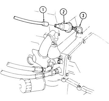 3. Connect lead 36A (1) to oil pressure sending unit (2).
FOLLOW-ON TASKS: Connect battery ground cable (para. 4-73).
Start engine (TM 9-2320-280-10) and check sending unit for leaks.
Install engine access cover (para. 10-15).
4-26. Fuel Pressure Transducer Replacement
This task covers: INITIAL SETUP: General mechanic's tool kit: TM 9-2320-280-10 automotive (Appendix B, Item 1) TM 9-2320-280-24P Materials/Parts Equipment Condition
a. Removal b. Installation
Tools Manual References
Sealing compound (Appendix C, Item 44) Battery ground cable disconnected (para. 4-73).
Hood raised and secured (TM 9-2320-280-10).
Note
The fuel pressure transducer is a sensor unit for diagnostic testing. It is mounted on top of the fuel filter on the firewall of the vehicle.
A. Removal
- Disconnect multiple connector (2) from STE/ICE-R wiring harness (3). 2. Remove fuel pressure transducer (1) from fuel filter (4).
b. Installation 1. Apply sealing compound to threads of fuel pressure transducer (1).
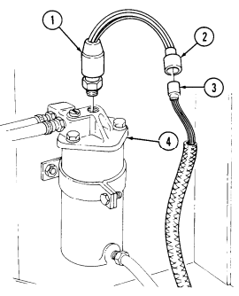 2. Install fuel pressure transducer (1) to fuel filter (4). 3. Connect multiple connector (2) to STE/ICE-R wiring harness (3).
FOLLOW-ON TASKS: Connect battery ground cable (para. 4-73).
Start engine (TM 9-2320-280-10) and check fuel pressure transducer for leaks.
Lower and secure hood (TM 9-2320-280-10).
4-27. Cold Advance Switch Replacement
This task covers: INITIAL SETUP:
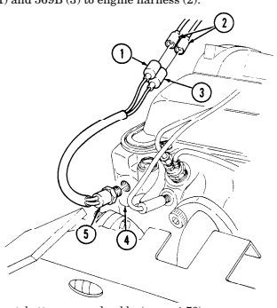
General mechanic's tool kit: TM 9-2320-280-24P automotive (Appendix B, Item 1) Sealing compound (Appendix C, Item 44)
a Removal b. Installation
Tools Manual References
Battery ground cable disconnected (para. 4-73). Engine coolant drained as necessary (para. 3-60). Engine access cover removed (para. 10-15).
| Equipment Condition |
|---|
The cold advcance switch is located in the right cylinder head water jacket at the rear of the cylinder head just above the exhaust manifold.
Prior to removal, tag leads for installation.
a. Removal 1. Disconnect leads 569G (1) and 569B (3) from engine harness (2). 2. Remove cold advance switch (5) from engine (4).
b. Installation 1.
Apply sealing compound to threads of cold advance switch (5). Install cold engine (4).
advance switch (5) in Connect leads 569G (1) and 569B (3) to engine harness (2).
FOLLOW-ON TASKS: Connect battery ground cable (para. 4-73).
Fill cooling system (para. 3-60). Install engine access cover (para. 10-15).
4-28. Fuel Level Sending Unit Replacement
This task covers: INITIAL SETUP:
Tools
General mechanic's tool kit: automotive (Appendix B, Item 1) Materials/Parts Five lockwashers (Appendix G, Item 139) Gasket (Appendix G, Item 45)
Manual References
TM 9-2320-280-10 TM 9-2320-280-24P
a. Removal b. Installation
Equipment Condition Fuel tank removed (para. 3-24).
General Safety Instructions Do not perform this procedure near fire, flames, or sparks.
Diesel fuel is highly flammable. Do not perform this procedure near fire, flame, or sparks. Severe injury or death will result.
A. Removal
- Remove five screws (1) and lockwashers (2) from fuel level sending unit (3) and fuel tank (6).
Discard lockwashers (2).
- Remove fuel level sending unit (3) from inside of fuel tank (6). 3. Remove and discard gasket (4).
b. Installation 1. Place gasket (4) on fuel level sending unit (3). 2. Install fuel level sending unit (3) into fuel tank (6) ensuring not to bend float arm (8). 3. Align holes of fuel level sending unit (3) to tank (6) so float (7) is pointed in same direction that tank filler neck (5) points.
- Secure fuel level sending unit (3) with five lockwashers (2) and screws (1). Tighten screws (1) to 32 lb-in. (4 N•m).

FOLLOW-ON TASKS: - Install fuel tank (para. 3-24).
- • Check fuel gauge for proper operation (TM 9-2320-280-10).
4-29. Glow Plug Controller/Temperature Sensor Replacement
This task covers: INITIAL SETUP: Tools General mechanic's tool kit: automotive (Appendix B, Item 1)
a. Removal b. Installation
| Manual References |
|---|
| TM 9-2320-280-1 |
TM 9-2320-280-10 TM 9-2320-280-24P
| Equipment Condition |
|---|
| · Battery ground c |
| · Hood raised and |
Materials/Parts Grease (Appendix C, Item 25) Sealing compound (Appendix C, Item 44)
-
Battery ground cable disconnected (para. 4-73). - Hood raised and secured (TM 9-2320-280-10).
-
It may be necessary to clamp surge tank-to-lower radiator tube to prevent loss of coolant.
-
Two different systems are used. One uses glow plug controller and the other uses a temperature sensor. The temperature sensor is indicated by a yellow band.
a. Removal 1. Disconnect multiple connector (2) from glow plug controller or temperature sensor (1). 2. Remove glow plug controller or temperature sensor (1) from water crossover (3).
b. Installation
-
Do not attempt to start engine unless controller/sensor is mounted in engine for a minimum of 10 minutes or if all glow plugs are disconnected. Damage to glow plugs may result.
-
Do not overtighten controller/sensor. Damage to crossover will result.
-
Apply sealing compound to threads of glow plug controller or temperature sensor (1). Install glow plug controller or temperature sensor (1) on water crossover (3). Tighten controller or sensor (1) to 14-20 lb-ft (19-27 N•m).
-
Apply grease to pins (4) of glow plug controller or temperature sensor (1). 3. Connect multiple connector (2) to glow plug controller or temperature sensor (1).
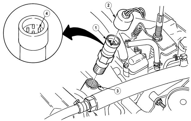
FOLLOW-ON TASKS: - Connect battery ground cable (para. 4-73).
- Lower and secure hood (TM 9-2320-280-10).
4-30. Fan Temperature Switch Replacement
This task covers:
A. Removal B. Installation
INITIAL SETUP: General mechanic's tool kit: TM 9-2320-280-10 automotive (Appendix B, Item 1) TM 9-2320-280-24P Tools Manual References Materials/Parts Equipment Condition Sealing compound (Appendix C, Item 44) Battery ground cable disconnected (para. 4-73).
Hood raised and secured (TM 9-2320-280-10).
NOTE The engine temperature switch is located on the top front side of the engine in the water crossover. Prior to removal, tag leads for installation.
a. Removal 1. Disconnect engine harness leads 458A (4) and 458B (3) from fan temperature switch (1). 2. Remove fan temperature switch (1) from water crossover (2).
b. Installation 1. Apply sealing compound to threads of fan temperature switch (1). Install fan temperature switch (1)
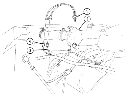
to water crossover (2).
- Connect engine harness leads 458A (4) and 458B (3) to fan temperature switch (1).
FOLLOW-ON TASKS: Connect battery ground cable (para. 4-73).
Lower and secure hood (TM 9-2320-280-10).
4-31. Time Delay Module Replacement
This task covers: INITIAL SETUP: Manual References TM 9-2320-280-10 TM 9-2320-280-24P
A. Removal
-
Disconnect connector plug (3) from control valve connector (5).
-
Disconnect connector plug (2) from engine harness (4). 3. Remove two screws (1) and time delay module (7) from cowl (6).
b. Installation 1. Install time delay module (7) on cowl (6) with two screws (1).

-
Connect connector plug (2) to engine harness (4).
-
Connect connector plug (3) to control valve connector (5).
FOLLOW-ON TASKS: Connect battery ground cable (para. 4-73).
Lower and secure hood (TM 9-2320-280-10).
A. Removal B. Installation
Tools Equipment Condition General mechanic's tool kit: Battery ground cable disconnected (para. 4-73).
automotive (Appendix B, Item 1) Hood raised and secured (TM 9-2320-280-10).
4-32. Rpm Sensor Replacement
This task covers: INITIAL SETUP: All vehicles except: M997A2, M1025A2, TM 9-2320-280-24P M1035A2, M1043A2, M1045A2, M1097A2 General mechanic's tool kit: automotive (Appendix B, Item 1)
A. Removal B. Installation
Applicable Models Manual References Equipment Condition Tools Engine access cover removed (para. 10-15).
A. Removal
- Disconnect harness connector (5) from RPM sensor connector (4). 2. Loosen nut (2) and remove RPM sensor (1) from oil pump drive (6).
b. Installation 1. Align tab (3) on RPM sensor (1) with slot (7) in oil pump drive (6). Install RPM sensor (1) on oil pump drive (6) with nut (2).
- Comect RPM sensor connector (4) to harness connector (5).
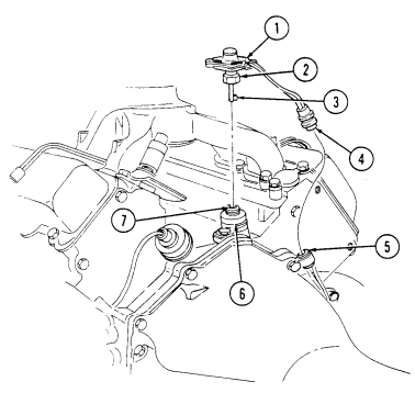
FOLLOW-ON TASK: Install engine access cover (para. 10-15).
4-33. Engine Rpm Sensor Replacement
This task covers: INITIAL SETUP: Applicable Models Manual References M997A2, M1025A2, M1035A2, M1043A2, TM 9-2320-280-10 M1045A2, M1097A2 TM 9-2320-280-24P
A. Removal A. Removal B. Installation
Tools Equipment Condition General mechanic's tool kit: Battery ground cable disconnected (para. 4-73).
automotive (Appendix B, Item 1) Hood raised and secured (TM 9-2320-280-10).
-
Disconnect engine harness leads (1) from RPM sensor leads (2).
-
Remove capscrew (3) and RPM sensor (4) from front cover (5).
b. Installation 1. Install RPM sensor (4) in front cover (5) with capscrew (3).
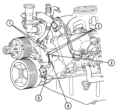 2. Connector RPM sensor leads (2) to engine harness leads (1).
FOLLOW-ON TASKS: Connect battery ground cable (para. 4-73) Lower and secure hood (TM 9-2320-280-10)
4-34. Backup Light Switch Replacement
This task covers: INITIAL SETUP: Applicable Models Material/Parts M1035, M1035A1, M1035A2 Manual References General mechanic's tool kit: Equipment Condition
A. Removal B. Installation
M996, M996A1, M997, M997A1, M997A2, Sealing compound (Appendix C, Item 44)
Tools TM 9-2320-280-24P
automotive (Appendix B, Item 1)Shift controls housing removed (para. 5-7 or 5-11).
- Remove boot (4) from shift control housing assembly (1).
Perform step 2 for M996, M996A1, M997, M997A1, M1035, and M1035A1 vehicles. Perform steps 3 and 4 for M997A2 and M1035A2 vehicles.
-
Remove backup light switch (3) from shift control housing assembly (1). 3. Remove two screws (6) and lockwashers (7) from backup light switch (8) and housing (1). Discard lockwashers (7).
-
Remove tiedown strap (10) and backup light switch (8) from neutral start switch (9).
b. Installation
Perform steps 1 through 3 for M997A2 and M1035A2 vehicles. Perform steps 4 and 5 for M996, M996A1, M997, M997A1, M1035, and M1035A1 vehicles.
Install backup light switch (8) on shift controls housing (1) with two lockwashers (7) and screws (6). Install tiedown strap (10) on leads from backup light switch (8) and neutral start switch (9). Position neutral start switch (9) leads and backup light switch (8) leads through boot (4) and install boot (4) on housing (1).
Apply sealing compound to threads of backup light switch (3), and install backup light switch on shift control assembly (1).
Position leads from neutral start switch (2), backup light switch (3), and shift selector indicator (5) through boot (4) and install boot (4) on shift control housing assembly (1).
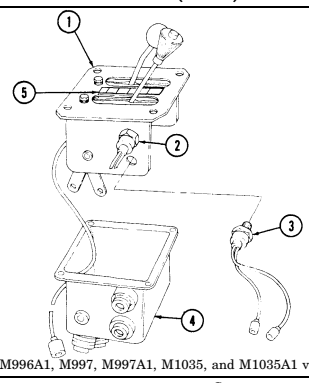
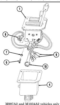
FOLLOW-ON TASK: Install shift controls housing (para. 5-7 or 5-11).
Section Iv. Transfer Case And Transmission Electrical Maintenance
| a. Removal | b. Installation |
|---|---|
| INITIAL SETUP: | |
| Tools | Equipment Condition |
| General mechanic's tool kit: | Fuel tank removed (para. 3-24). |
| automotive (Appendix B, Item 1) | General Safety Instructions |
| Materials/Parts | Do not perform this procedure near fire, flames, or |
| Five lockwashers (Appendix G, Item 139) | sparks. |
| Gasket (Appendix G, Item 45) | |
| Manual References | |
| TM 9-2320-280-10 | |
| TM 9-2320-280-24P | |
| WARNING | |
| Diesel fuel is highly flammable. Do not perform this procedure | |
| near fire, flame, or sparks. Severe injury or death will result. | |
| a. Removal | |
| 1. | Remove five screws (1) and lockwashers (2) from fuel level sending unit (3) and fuel tank (6). |
| Discard lockwashers (2). | |
| 2. Remove fuel level sending unit (3) from inside of fuel tank (6). | |
| 3. Remove and discard gasket (4). | |
| b. Installation |
4-36. Transfer Case Indicator Switch Replacement
This task covers:
A. Removal B. Installation
INITIAL SETUP: Applicable Models Equipment Condition M1097, "A1" and "A2" series Battery ground cable disconnected (para. 4-73).
Tools General mechanic's tool kit: automotive (Appendix B, Item 1)
A. Removal
-
Disconnect leads 511A (4) and 511B (5) from indicator switch leads (3) on transfer case (1).
-
Remove indicator switch (2) from transfer case (1).
b. Installation 1. Install indicator switch (2) on transfer case (1).
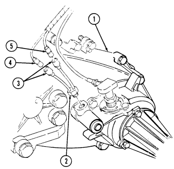
- Connect leads 511A (4) and 511B (5) to indicator switch leads (3).
FOLLOW-ON TASK: Connect battery ground cable (para. 4-73).
4-37. Transfer Case Indicator Lamp Cable Assembly Replacement
This task covers:
A. Removal B. Installation Initial Setup:
| General mechanic's tool kit: | Battery ground cable disconnected (para. 4-73). |
|---|---|
| automotive (Appendix B, Item 1) | Hood raised and secured (TM 9-2320-280-10). |
| Manual References | |
| TM 9-2320-280-10 | |
| TM 9-2320-280-24P |
A. Removal
- Disconnect leads 511A (6) and 511B (7) from indicator switch leads (5) on transfer case (3). 2. Deleted. 3. Disconnect lead 511A (8) from lamp assembly lead (9). 4. Disconnect leads 458B (12) and 458C (11) from fan temperature switch lead (13) and engine wiring harness lead 458A (10) and remove cable assembly (1) from vehicle.
B. Installation
-
Position cable assembly (1) in approximate mounting location on vehicle. 2. Connect leads 458B (12) and 458C (11) to fan temperature switch lead (13) and engine wiring harness lead 458A (10).
-
Connect lead 511A (8) to lamp assembly lead (9). 4. Connect leads 511B (7) and 511A (6) to indicator switch leads (5) on transfer case (3). 5. Deleted.
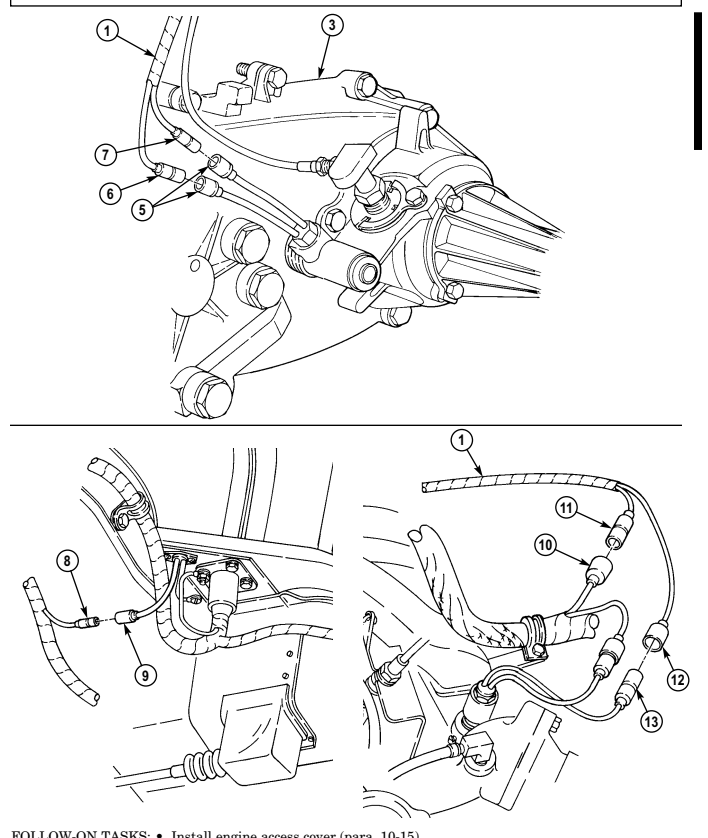
FOLLOW-ON TASKS: - • Install engine access cover (para. 10-15).
- • - • Connect battery ground cable (para. 4-73).
4-37. TRANSFER CASE INDICATOR LAMP CABLE ASSEMBLY REPLACEMENT (Cont'd)
4-38. Transfer Case Indicator Lamp Assembly Replacement
This task covers: INITIAL SETUP: Applicable Models Manual References M1097, "A1" and "A2" series TM 9-2320-280-24P
A. Removal
-
Disconnect lead 511A (5) from lamp assembly lead (4).
-
Remove screw (3) and ground lead (2) from engine (8). 3. Remove two screws (6) and lamp assembly (7) from body (1).
b. Installation
A. Removal B. Installation
Tools Equipment Condition
General mechanic's tool kit: Battery ground cable disconnected (para. 4-73).
automotive (Appendix B, Item 1) Engine access cover removed (para. 10-15).
- Install lamp assembly (7) to body (1) with two screws (6).
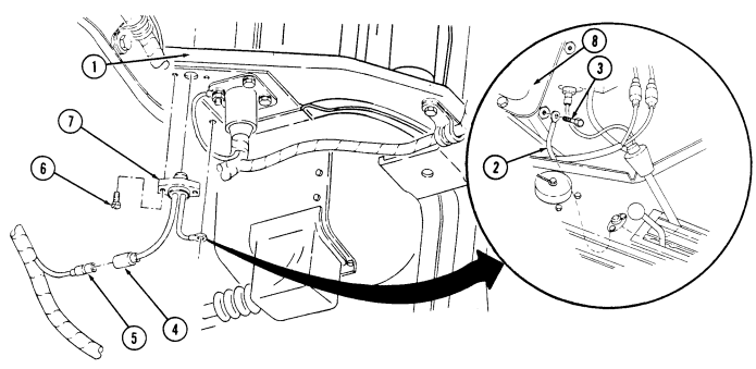
- Install ground lead (2) to engine (8) with screw (3). 3. Connect lead 511A (5) to lamp assembly lead (4).
FOLLOW-ON TASKS: Install engine access cover (para. 10-15). Connect battery ground cable (para. 4-73).
4-39. Transmission Indicator Lamp Assembly Replacement (4L80-E)
This task covers: INITIAL SETUP: Applicable Models Manual References M997A2, M1025A2, M1035A2, TM 9-2320-280-24P automotive (Appendix B, Item 1)
a. Removal b. Installation
M1043A2, M1045A2, M1097A2Equipment Condition
Tools Battery ground cable disconnected (para. 4-73).
General mechanic's tool kit: Engine access cover removed (para. 10-15).
a. Removal 1. Disconnect lead 657 (4) from lamp assembly lead (3).
- Remove two screws (2) and lamp assembly (5) from body (1).
b. Installation 1. Install lamp assembly (5) to body (1) with two screws (2).
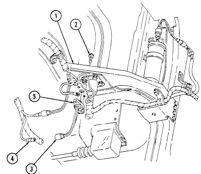
- Connect lead 657 (4) to lamp assembly lead (3).
FOLLOW-ON TASKS: Install engine access cover (para. 10-15).
Connect battery ground cables (para. 4-73).
4-40. Transmission Circuit Breakers And Jumper Leads Replacement (4L80-E)
This task covers: INITIAL SETUP:
A. Removal B. Installation
Applicable Models Manual References M997A2, M1025A2, M1035A2, TM 9-2320-280-24P M1043A.2, M1045A2, M1097A2 General mechanic's tool kit: automotive (Appendix B, Item 1) Equipment Condition Tools Battery ground cables discomected (para. 4-73).
Prior to removal, tag leads for installation.
A. Removal
1.Remove nut (6), capscrew (1), cable (2), three circuit breaker-to-battery leads (3) and cable (4) from terminal clamp (5).
NOTE The coverplate on M1025A2 and M1043A2 vehicles has four capscrews and washers.
Remove five capscrews (8), two washers (10), and coverplate (7) from "B" pillar (9).
Remove three screws (20) and circuit breaker-tubattery leads (3) from circuit breakers (21), (16), and (15).
Remove two screws (12) and circuit breaker-to-relay leads (13) from circuit breakers (16) and (21).
Discomect leads (13) from relay lead (19) and remove leads (13). Remove screw (12) and circuit breaker-to-harness lead (14) from circuit breaker (15). Remove two nuts (11), capscrews (18), washers (17) and circuit breaker (21) from coverplate (7). Repeat step 7 for circuit breakers (15) and (16).
B. Installation
- Install circuit breaker (21) on coverplate (7) with two washers (17), capscrews (18), and nuts (11).
Repeat step 1 for circuit breakers (15) and (16).
-
Install circuit breaker-to-harness lead (14) on circuit breaker (15) with screw (12).
-
Connect leads (13) to relay lead (19).
-
Install two circuit breaker-to-relay leads (13) to circuit breakers (16) and (21) with screws (12).
-
Install three circuit breaker-to-battery leads (3) on circuit breakers (15) (16), and (21) with screws (20). 6. Install coverplate (7) to "B" pillar (9) with two washers (10) and five capscrews (8). 7. Install cable (4), three circuit breaker-to-battery leads (3) and cable (2) to terminal clamp (5) with capscrew (1) and nut (6).
4-40. Transmission Circuit Breakers And Jumper Leads Replacement (4L80-E) (Cont'D)
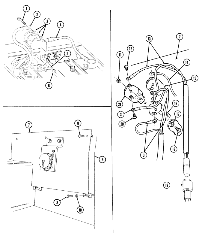
FOLLOW-ON TASK: Connect battery ground cables (para. 4-73).
4-41. Transmission Relay Replacement (4L80-E)
This task covers: INITIAL SETUP: Applicable Models Manual References M997A2, M1025A2, M1035A2, TM 9-2320-280-24P M1043A2, M1045A2, M1097A2Equipment Condition General mechanic's tool kit: automotive (Appendix B, Item 1) a. Removal b. Installation Tools Battery ground cables disconnected (para. 4-73).
Prior to removal, tag leads for installation. M1025A2 and M1043A2 vehicles have four capscrews and washers on coverplate.
a. Removal 1. Remove five capscrews (2), two washers (4) and coverplate (1) from "B" beam (3).
-
Disconnect four leads (5) from relay leads (6).
-
Remove two nuts (9), washers (10), capscrews (7), and relay (8) from coverplate (1).
b. Installation 1. Install relay (8) on coverplate (1) with two capscrews (7), washers (10), and nuts (9).
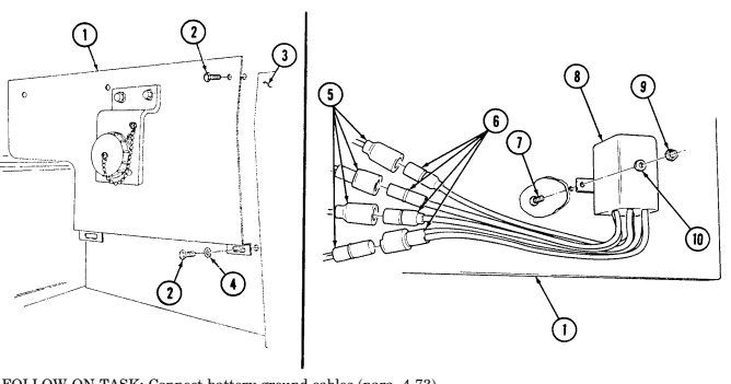 2. Connect four relay leads (6) to leads (5). 3. Install coverplate (1) to "B" beam (3) with two washers (4) and five capscrews (2).
FOLLOW-ON TASK: Connect battery ground cables (para. 4-73).
4 - 4 2 . Transmission Control Module (Tcm) Replacement (4L80-E)
This task covers: INITIAL SETUP: Applicable Models M997A2, M1025A2, M1035A2, M1043A2, M1045A2, M1097A2, M1123 Tools General mechanic's tool kit: automotive (Appendix B, Item 1) Personnel Required One mechanic One assistant a. Removal
A. Removal B. Installation
Manual References TM 9-2320-280-24P Equipment Condition
- Battery ground cables disconnected (para. 4-73). - Left rear seat compartment cover removed (para. 10-43).
Ensure that ignition switch is OFF before disconnecting or reconnecting the Transmission Control Module (TCM). Failure to do this may cause internal damage to TCM.
- Disconnect harness connector (1) from TCM (2). 2. Remove four nuts (4), washers (3), and TCM (2) from body (5).
b. Installation 1. Install TCM (2) on body (5) with four washers (3) and nuts (4).
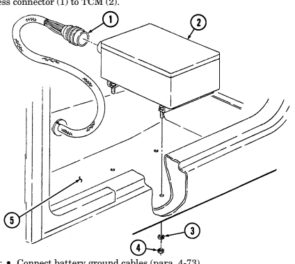 2. Connect harness connector (1) to TCM (2).
FOLLOW-ON TASKS: - Connect battery ground cables (para. 4-73).
- Install left rear seat compartment cover (para. 10-43).
4 - 4 2 . 1 . E-Prom Replacement
| Applicable Models |
|---|
This task covers:
| INITIAL SETUP: |
|---|
M997A2, M1025A2, M1035A2, M1043A2, M1045A2, M1097A2, M1123 Tools General mechanic's tool kit: automotive (Appendix B, Item 1) Materials/Parts RTV sealant (Appendix C, Item 38) a. Removal
a. Removal b. Installation
| Manual References |
|---|
| TM 9-2320-280-2 |
Equipment Condition
- Battery ground cables disconnected (para. 4-73). - Left rear seat compartment cover removed (para. 10-43).
Ensure that ignition switch is OFF before replacing E-PROM or disconnecting or reconnecting the Transmission Control Module (TCM). Failure to do this may cause internal damage to TCM.
For proper calibration of E-PROM to transmission, ensure E-PROM is the same production year as the transmission installed in the vehicle.
- Loosen four screws (1) and remove cover (2) and foam insulation (4) from TCM box (8). 2. Remove two screws (5) and access panel (6) from terminal box (9). 3. Remove E-PROM (10) from circuit board (7).
B. Installation
- Install E-PROM (10) on circuit board (7) by pushing it down firmly to ensure it is well seated. 2. Install access panel (6) on terminal box (9) with two screws (5). 3. Clean sealant from TCM box (8) and cover (2). 4. Apply 0.125 in. (3.175 mm) bead of RTV adhesive sealant in groove (3) on cover (2). 5. Install foam insulation (4) and cover (2) on TCM box (8) and tighten four screws (1) to 30 lb-in.
(3 N•m).
4-42.1. E-Prom Replacement (Contd)
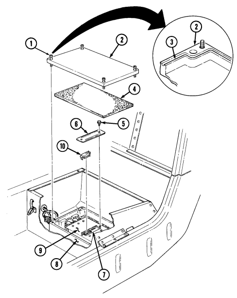
FOLLOW-ON TASKS: - • Connect negative battery cables (para. 4-73).
- • - • - Install left rear seat compartment cover (para. 10-43).
4 - 4 3 . Kick-Down Switch Maintenance (3L80)
This task covers: b. Installation
Initial Setup:
Applicable Models All vehicles except: M997A2, M1025A2, M1035A2, M1043A2, M1045A2, M1097A2, M1123 Tools General mechanic's tool kit: automotive (Appendix B, Item 1) Test Equipment Multimeter (Appendix B, Item 166) a. Removal c. Adjustment Manual References TM 9-2320-280-10 TM 9-2320-280-24P Equipment Condition
- Battery ground cable disconnected (para. 4-73). - Hood raised and secured (TM 9-2320-280-10).
a. Removal 1. Disconnect engine harness leads 315A (5) and 315B (4) from kick-down switch (3). 2. Remove two capscrews (1) and switch (3) from fuel injection pump (2).
b. Installation 1. Install kick-down switch (3) on injection pump (2) with two capscrews (1). 2. Connect leads 315A (5) and 315 B (4) to kick-down switch (3).
c. Adjustment
Kick-down switch must be adjusted whenever it is replaced or when injection pump is replaced.
- Disconnect throttle return spring (6) from throttle shaft lever (7) and accelerator cable bracket (9). 2. Disconnect engine harness leads 315A (5) and 315 B (4) from kick-down switch (3). 3. Connect multimeter to leads on kick-down switch (3) to read continuity. 4. Loosen two capscrews (1) to allow movement of kick-down switch (3).
8 . Position feeler gauge set at 0.310 in. (7.874 mm) between throttle shaft lever (7) and injection pump (2) ensuring feeler gauge does not touch screw (8).
- Move throttle shaft lever (7) to wide open position so throttle shaft lever (7) rests on feeler gauge.
Note multimeter, no continuity should be present. If continuity is present, repeat steps 3 through 8.
-
Connect leads 315A (5) and 315 B (4) to kick-down switch (3).
-
Connect throttle return spring (6) to accelerator cable bracket (9) and throttle shaft lever (7).
5 . Position feeler gauge set at 0.295 in. (7.493 mm) between throttle shaft lever (7) and injection pump (2) ensuring feeler gauge does not touch screw (8).
- Move throttle shaft lever (7) to wide open position so throttle shaft lever (7) rests on feeler gauge. 7. Rotate kick-down switch (3) slowly until multimeter reads continuity through kick-down switch (3) and tighten capscrews (1).
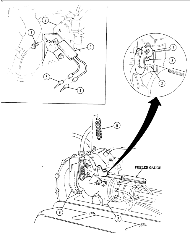
FOLLOW-ON TASKS: - Connect battery ground cable (para. 4-73).
- • - • - - - - - - - Lower and secure hood (TM 9-2320-0280-10).
4-44. Fan Cut-Off Switch Replacement (4L80-E)
| This task covers: |
|---|
INITIAL SETUP: Applicable Models _______________ M997A2, M1025A2, M1035A2, M1043A2, M1045A2, M1097A2 Tools General mechanic's tool kit: automotive (Appendix B, Item 1)
Materials/Parts
Two lockwashers (Appendix G, Item 135) a. Removal
| (para. 4-73). |
|---|
| Manual References |
|---|
a. Removal b. Installation
- Engine access cover removed (para. 10-15). - Battery ground cable disconnected (para. 4-73). - Hood raised and secured (TM 9-2320-280-10).
Prior to removal, tag leads for installation.
-
Slide rod (1) forward and disconnect from fuel injection pump (2). 2. Remove rod (1) from switch (11). 3. Disconnect harness leads 315A/315B (10) from leads 315 (9). 4. Remove two nuts (13), lockwashers (12), washers (8), capscrews (7), washers (8), and switch (11) from bracket (5). Discard lockwashers (12).
-
Remove two capscrews (3), leads (4), and bracket (5) from engine (6).
B. Installation
-
Install switch (11) on bracket (5) with two washers (8), capscrews (7), washers (8), lockwashers (12), and nuts (13). Do not tighten nuts (13).
-
Slide rod (1) forward and connect to fuel injection pump (2). 3. Install rod (1) on switch (11). 4. Install bracket (5) and two leads (4) on engine (6) with capscrews (3). 5. Position rod (1) at wide open throttle and position switch (11) to close. Tighten nuts (13). 6. Connect harness leads 315A/315B (10) to leads 315 (9).
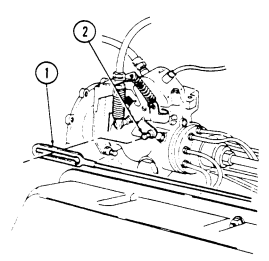
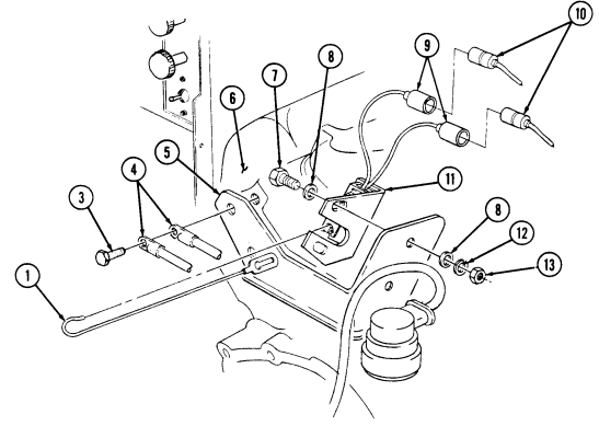
FOLLOW-ON TASKS:
-
Install engine access cover (para. 10-15).
-
Connect battery ground cable (para. 4-73).
-
Lower and secure hood (TM 9-2320-280-10).
4 - 4 5 . Throttle Position (Tp) Sensor Maintenance (4L80-E)
This task covers: a. Removal c. Adjustment b. Installation
Initial Setup:
Applicable Models M997A2, M1025A2, M1035A2, M1043A2, M1045A2, M1097A2, M1123 Tools General mechanic's tool kit: automotive (Appendix B, Item 1) Test Equipment Multimeter (Appendix B, Item 166) Jumper wire (Appendix B, Item 93.1) Gauge block (Appendix B, Item 63) a. Removal Manual References TM 9-2320-280-10 TM 9-2320-280-24P Equipment Condition - Hood raised and secured (TM 9-2320-280-10). - Battery ground cables disconnected (para. 4-73).
The Throttle Position (TP) sensor is an electrical component and must not be soaked in any liquid cleaner or solvent or damage may result.
- Disconnect body wiring harness connector (3) from TP sensor connector (4). 2. Remove two screws (7), washers (6), and TP sensor (5) from fuel injection pump (1).
b. Installation 1. Ensuring throttle is closed, place TP sensor (5) on throttle shaft (2) of fuel injection pump (1). 2. Rotate TP sensor (5) counterclockwise to align screw holes in sensor (5) with holes in injection pump (1).
-
Install TP sensor (5) on injection pump (1) with two washers (6) and screws (7). Do not tighten screws (7).
-
Adjust TP sensor (5) (para. 4-45c).
c. Adjustment 1. Disconnect engine harness connector (12) and body harness connector (11). 2. Install jumper wires between TP sensor connector (4) and body wiring harness connector (11). 3. Rotate ignition switch to RUN position (TM 9-2320-280-10). 4. Using a digital multimeter, measure voltage between terminals A and C of TP sensor connector (4). This voltage should be between 4.5 - 5.8 volts. Multiply by 0.33 to obtain the desired TP sensor voltage, and use this figure to adjust TP sensor.
Note
For example, 5.00 volts x 0.33 = 1.65 volts (±1% or 0.02 volt tolerance).
5 . Install 0.646 side of gauge block between injection pump throttle lever stopscrew (8) and housing boss (9) on injection pump (1).
4 - 4 5 . Throttle Position (Tp) Sensor Maintenance (4L80-E) (Cont'D)
- Rotate injection pump throttle lever (10) so that stopscrew (8) holds gauge block against housing boss (9).
Note
Keep throttle lever in this position during remainder of adjustment steps.
- Measure voltage between terminals B and C of TP sensor connector (4).
a. If measured voltage is within calculated specification, as indicated in step 4, remove jumper wire and connect body harness connector (3) to TP sensor connector (4).
b. If voltage is not within calculated specification, go to next step.
-
Loosen TP sensor mounting screws (7) and rotate TP sensor (5) toward rear of vehicle (counterclockwise direction).
-
With voltmeter connected to terminals B and C of TP sensor connector (4), rotate TP sensor (5) slowly toward front of vehicle (clockwise direction) until voltmeter indicates voltage as determined in step 4.
-
Tighten TP sensor mounting screws (7) and confirm that adjustment did not change.
-
Remove jumper wire.
-
Remove gauge block. 13. Connect body wiring harness connector (3) to TP sensor connector (4).
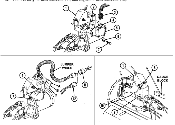 14. Connect body harness connector (11) and engine harness connector (12).
FOLLOW-ON TASKS: - Lower and secure hood (TM 9-2320-280-10).
- Connect battery ground cables (para. 4-73).
4-46. Transmission Input Speed Sensor (Tiss) And Output Speed Sensor
(TOSS) MAINTENANCE (4L80-E) This task covers: a. Removal c. Installation b. Inspection INITIAL SETUP: Applicable Models M997A2, M1025A2, M1035A2, M1043A2, M1045A2, M1097A2, M1123 Tools General mechanic's tool kit: automotive (Appendix B, Item 1)
Materials/Parts
Packing retainer (Appendix G, Item 230) Hydraulic fluid (Appendix C, Item 27) Manual References TM 9-2320-280-10 TM 9-2320-280-24P Equipment Conditions Battery ground cable disconnected (para. 4-73).
a. Removal
Both the input and output speed sensors are replaced basically the same.
- Disconnect speed sensor harness connector (3) from sensor (5). 2. Remove capscrew (7) from sensor (5) and transmission (1). Slide bracket (6) off sensor (5). 3. Remove harness clip (2) from sensor bracket (6). 4. Using a twisting motion, remove sensor (5) from transmission (1).
b. Inspection Inspect packing retainer (4), and replace if damaged.
c. Installation 1. Lubricate packing retainer (4) with hydraulic fluid and install on sensor (5) if removed. 2. Install harness clip (2) on sensor bracket (6). 3. Using a twisting motion, install sensor (5) in transmission (1). 4. Slide bracket (6) over sensor (5) and install capscrew (7). 5. Install connector (3) on sensor (5).
4-46. TRANSMISSION INPUT SPEED SENSOR (TISS) AND OUTPUT SPEED SENSOR (TOSS) MAINTENANCE (4L80-E) (Cont'd)
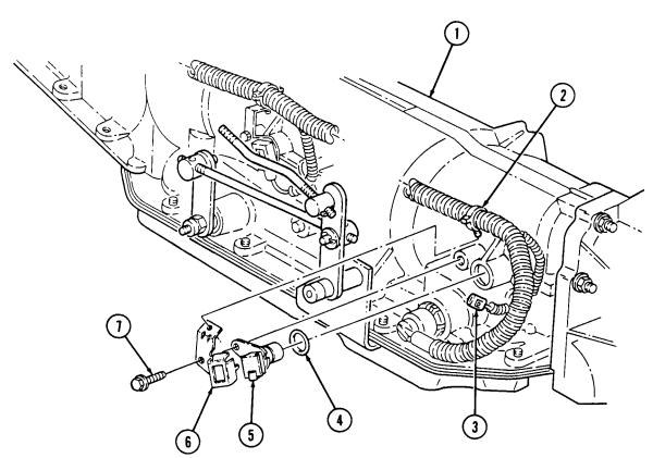
· Connect battery ground cable (para. 4-73).
FOLLOW-ON TASK:
Section V. Lighting System Maintenance 4 - 4 7 . Lighting System Maintenance Task Summary
| Applicable Models Manual References | |
|---|---|
| M1097, "A1" and "A2" series | TM 9-2320-280-24P |
| Tools | Equipment Condition |
| General mechanic's tool kit: | Battery ground cable disconnected (para. 4-73). automotive (Appendix B, Item 1) Engine access cover removed (para. 10-15). |
| a. Removal | |
| 1. Disconnect lead 511A (5) from lamp assembly lead (4). | |
| 2. Remove screw (3) and ground lead (2) from engine (8). | |
| 3. Remove two screws (6) and lamp assembly (7) from body (1). | |
| b. Installation | |
| Install lamp assembly (7) to body (1) with two screws (6). | 1. |
| 2. | Install ground lead (2) to engine (8) with screw (3). |
| 3. Connect lead 511A (5) to lamp assembly lead (4). |
4-48 Service Headlight Lamp Maintenance
This task covers: a. Removal c. Adjustment b. Installation INITIAL SETUP: Tools General mechanic's tool kit: automotive (Appendix B, Item 1) Personnel Required One mechanic One assistant Materials/Parts Chalk (Appendix C, Item 15) Manual References TM 9-2320-280-10 TM 9-2320-280-24P TM 43-0139 Equipment Condition Battery ground cable disconnected (para. 4-73).
Note
Prior to removal, tag leads for installation.
a. Removal 1. Loosen three retaining right screws (1). 2. Remove retaining ring (2).
Note
If retaining ring shows signs of corrosion, perform steps 3 through 5 to allow accumulated water/condensation to drain out.
-
Clean and remove dirt/rust conditions from surface of retaining ring (2). 4. Drill a 9/16-in. (14 mm) hole in bottom of retaining ring (2), 3/4 in. (19 mm) from inside edge of retaining ring (2).
-
Paint all unprotected areas (TM 43-0139). 6. Disconnect leads 17 (4), 18 (6), and 91 (7) from headlight housing (5) and remove lamp (3).
b. Installation
Note
Circuit numbers are marked on housing.
- Connect leads 17 (4), 18 (6), and 91 (7) to headlight housing (5). 2. Install lamp (3) to housing (5) and secure with retaining ring (2) and three screws (1).
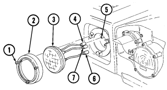 3. Connect battery ground cable (para. 4-73).
c. Adjustment
-
Headlamp alignment is the same for both headlamps. - Inflate tires on vehicle before starting procedure (TM 9-2320-280-10).
-
Measured height (H) varies depending on model of vehicle and load configuration.
-
Position vehicle on level ground 25 ft (8 M) from and facing a vertical wall. 2. Measure height (H) from ground up to center of lamp (3). 3. Using chalk, draw a horizontal line across vertical wall at center height (H) of lamp (3). 4. Draw a vertical line through horizontal line for center position (C) of vehicle. 5. Measure distance from center to center of lamp (3) and divide measurement in half. 6. Draw two vertical lines (D) at equal distance from center position line (C). 7. Measure down 1/12 from horizontal line (H) and mark horizontal lines through lamp vertical lines (D).
-
Turn headlamps on low beam and block out one lamp (3). 9. Adjust lamp (3) using vertical adjusting screw (8) and/or horizontal adjusting screw (9) until center of lamp beam is aligned with lower horizontal and vertical lines.
-
Repeat steps 8 and 9 for other lamp (3).
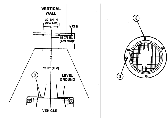
FOLLOW-ON TASK: Check headlight lamp for proper operation (TM 9-2320-280-10).
4-49. Service Headlight Assembly Replacement
This task covers:
A. Removal B. Installation
INITIAL SETUP: Tools General mechanic's tool kit: automotive (Appendix B, Item 1) Manual References TM 9-2320-280-10 TM 9-2320-280-24P
Equipment Condition
-
Battery ground cable disconnected (para. 4-73).
-
Hood raised and secured (TM 9-2320-280-10).
-
Prior to removal, tag leads for installation. - Note position of circuit 91 for installation.
A. Removal
- Remove three nuts (4) and washers (5) from headlight assembly (1) and hood (6). 2. Remove leads 17 (2), 18 (3), and 91 (7) from headlight assembly (1). 3. Remove headlight assembly (1) from hood (6).
b. Installation
Circuit numbers are marked on headlight next to respective connector.
- Connect leads 17 (2), 18 (3), and 91 (7) to headlight assembly (1). 2. Install headlight assembly (1) to hood (6) with three washers (5) and nuts (4).
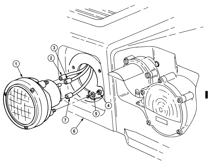
FOLLOW-ON TASKS: - Connect battery ground cable (para. 4-73).
- Lower and secure hood (TM 9-2320-280-10). · Check adjustment of headlight lamp (para. 4-48).
4-50. Blackout Drive Light Assembly Replacement
This task covers:
| Materials/Parts |
|---|
| General mechanic's tool kit: |
|---|
| automotive (Appendix B, Item 1) |
| INITIAL SETUP: |
|---|
Tools
Lockwasher (Appendix G, Item 133) Four plain-assembled nuts (Appendix G, Item 204) Antiseize compound (Appendix C, Item 13)
a. Removal b. Installation
Equipment Condition
| Manual References |
|---|
| TM 9-2320-280-10 |
| TM 9-2320-280-24P |
- Battery ground cable disconnected (para. 4-73). - Hood raised and secured (TM 9-2320-280-10).
A. Removal
- Remove nut (5), lockwasher (6), and special washer (7) from blackout drive light (1) and hood (9).
Discard lockwasher (6).
- Disconnect lead 198 (4) from blackout drive light (1). 3. Remove blackout drive light (1) and coned mounting washer (2) from swivel bracket (11). 4. Disconnect lead 92C (3) from blackout drive light (1).
Some vehicles may have screws in place of studs securing bracket and plate to hood.
- Remove four plain-assembled nuts (8), swivel bracket (11), and plate (10) from hood (9). Discard plain-assembled nuts (8).
b. Installation
Some vehicles may have screws in place of studs securing bracket and plate to hood.
-
Install swivel bracket (11) to outside of hood (9), and plate (10) to inside of hood (9) with four plainassembled nuts (8). Tighten plain-assembled nuts (8) 16-30 lb-in. (1-3 N•m).
-
Connect lead 92C (3) to blackout drive light (1). 3. Place blackout drive light (1) and coned mounting washer (2) through hole in swivel bracket (11). 4. Connect lead 198 (4) to blackout drive light (1). 5. Install blackout drive light (1) on hood (9) with special washer (7), lockwasher (6), and nut (5).
4-50. Blackout Drive Light Assemlby Replacement (Cont'D)
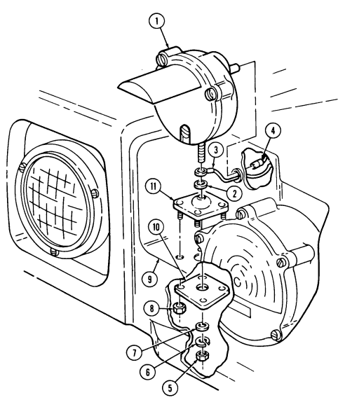
FOLLOW-ON TASKS: · · Connect battery ground cable (para. 4-73).
· Lower and secure hood (TM 9-2320-280-10).
- Check blackout drive light for properoperation (TM 9-2320-280-10).
4-51. Blackout Drive Light Lamp Replacement
This task covers:
Initial Setup:
Tools General mechanic's tool kit: automotive (Appendix B, Item 1) Materials/Parts Three gaskets (Appendix G, Item 46) Gasket (Appendix G, Item 56) Adhesive sealant (Appendix C, Item 10) a. Removal b. Installation
| TM 9-2320-280-24P |
|---|
| Equipment Condition |
| - Left rear seat compartment cover removed |
| (para. 10-43). |
a. Removal 1. Loosen three retaining screws (2) from light door (6). 2. Remove light door (6), three gaskets (5.1), and gasket (3) from light body (5). Discard gasket (3) and gaskets (5.1).
- Remove lamp (4). 4. Clean mating surface on light door (6) and light body (5). Remove sealant.
b. Installation 1. Install lamp (4). 2. Install three gaskets (5.1), gasket (3), and light door (6) to light body (5) with lens hood (1) at top.
NOTE To prevent moisture from entering light assembly, tighten all screws evenly.
- Secure light door (6) by tightening three screws (2). 4. Apply thin coat of sealant to seam between light body (5) and light door (6).
4-51. Blackout Drive Light Lamp Replacement (Cont'D)
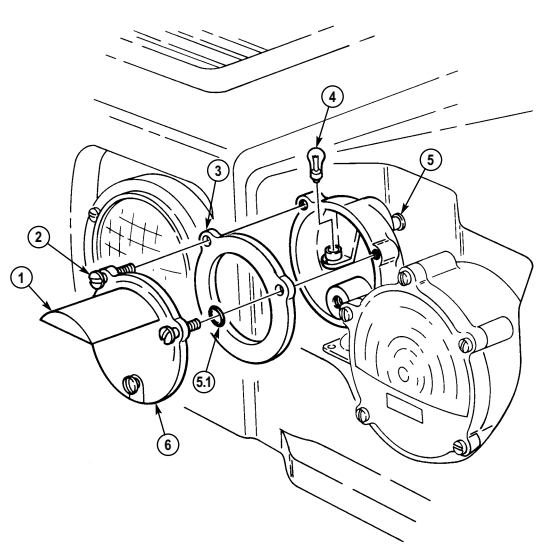
FOLLOW-ON TASKS: - Connect battery ground cable (para. 4-73).
· Check blockout drive light for proper operation (TM 9-2320-280-10).
4-52. Front Composite Light Assembly Replacement
This task covers: INITIAL SETUP: Tools General mechanic's tool kit: automotive (Appendix B, Item 1) Materials/Parts Adhesive sealant (Appendix C, Item 10)
A. Removal B. Installation
Manual References TM 9-2320-280-10 TM 9-2320-280-24P Equipment Condition _________________ Battery ground cable disconnected (para. 4-73).
-
The procedure to remove and install right and left composite light assemblies is basically the same except left side has four screws securing close-off cover and right side has three screws. This procedure covers the left composite light.
-
Prior to removal, tag leads for installation.
a. Removal 1. Remove four screws (1), washers (2), and close-off cover (3) from hood (4). 2. Disconnect leads 20 (5), 461 (12), and 491 (11) from hood wiring harness (6). 3. Remove two capscrews (9), washers (8), ground 92 (7), buss bar (10), and composite light (13) from hood (4).
b. Installation
To prevent water from accumulating between the composite light access cover and the hood, general purpose RTV adhesive sealant should be applied to the inside of the cover. Clean and reapply RTV when removing and reinstalling the cover.
-
Install composite light (13), buss bar (10), and ground 92 (7) on hood (4) with two washers (8) and capscrews (9).
-
Connect lead 20 (5), 461 (12), and 491 (11) to hood wiring harness (6). 3. Install close-off cover (3) to hood (4) with four washers (2) and screws (1).
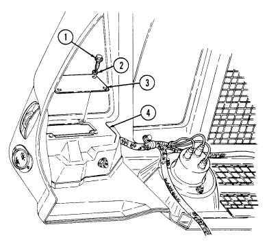
4-52. Front Composite Light Assembly Replacement (Cont'D)
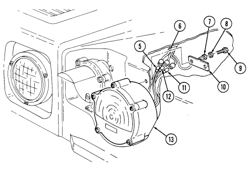
FOLLOW-ON TASKS: - Connect battery ground cable (para. 4-73).
- • - • Lower and secure hood (TM 9-2320-280-10).
· Check front composite light for proper operation (TM 9-2320-280-10).
4-53. Front Composite Light Lamp Replacement
This task covers: INITIAL SETUP: Tools General mechanic's tool kit: automotive (Appendix B, Item 1) Materials/Parts O-ring (Appendix G, Item 220) Adhesive sealant (Appendix C, Item 10) a. Removal 1. Loosen five retaining screws (1) and remove light door (2) and O-ring (5) from light body (3).
Discard O-ring (5).
- Remove lamp (4). 3. Clean mating surface on light door (2) and light body (3). Remove sealant.
b. Installation 1. Install lamp (4).
To prevent moisture from entering light assembly, tighten all screws evenly.
- Install O-ring (5) and light door (2) on light body (3) with five retaining screws (1). 3. Apply thin coat of sealant to seam between light body (3) and light door (2).
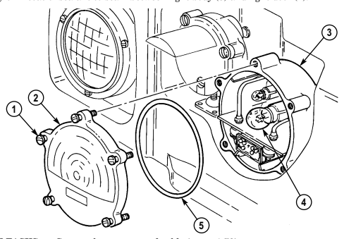
FOLLOW-ON TASKS: - Connect battery ground cable (para. 4-73).
- Check front composite light for proper operation (TM 9-2320-280-10).
4-88 Change 3
a. Removal b. Installation
Manual References TM 9-2320-280-10 TM 9-2320-280-24P Equipment Condition Battery ground cable disconnect (para. 4-73).
4-54. Side Marker Light Lens And Lamp Replacement
This task covers: a. Lens and Lamp Removal b. Lens and Lamp Installation INITIAL SETUP: automotive (Appendix B, Item 1) Tools Equipment Condition General mechanic's tool kit: Battery ground cable disconnect (para. 4-73).
Manual References TM 9-2320-280-10 TM 9-2320-280-24P
A. Lens And Lamp Removal
-
Remove two screws (5), door (4) and lens (3) from light body (1).
-
Remove lamp (2).
b. Lens and LamII Installation 1.
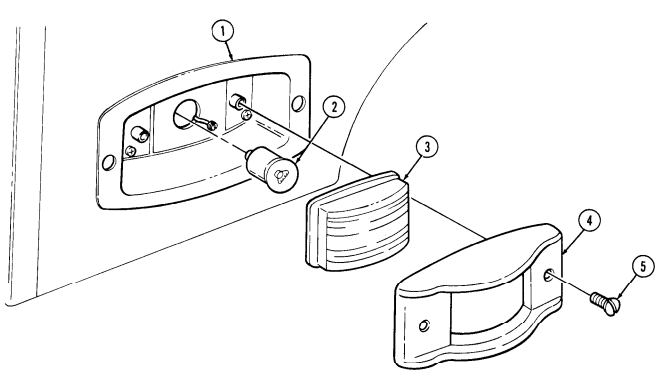
Install lamp (4). Install lens (3) and door (4) on light body (1) with two screws (5).
FOLLOW-ON TASKS: Connect battery ground cable (para. 4-73).
Check side marker light for proper operation (TM 9-2320-280-10).
4-55. Side Marker Light Assembly Replacement
This task covers: INITIAL SETUP: Tools General mechanic's tool kit: automotive (Appendix B, Item 1) Materials/Parts Four locknuts (Appendix G, Item 74) (front only)
a. Removal b. Installation
Manual References TM 9-2320-280-10 TM 9-2320-280-24P Equipment Condition
- Battery ground cable disconnect (para. 4-73). - Hood raised and secured (front side marker only) (TM 9-2320-280-10).
Procedures to remove and install the front and rear side marker light assemblies are basically the same for all models. Front marker lights have locknuts, rear marker lights have plain nuts. This procedure is for the left front side marker for basic and A1 models.
A. Removal
- Remove four screws (1), washers (2), and close-off cover (3) from hood (4). 2. Disconnect lead 489 (14) from hood wiring harness (15). 3. Remove two screws (13), lens (11), and door (12) from side marker light (9) 4. Remove four screws (10), washers (6), locknuts (5), ground 92 (7), gasket (8), and side marker light (9) from hood (4). Discard locknuts (5).
B. Installation
-
Install gasket (8), side marker light (9), and ground 92 (7) on hood (4) with four screws (10), washers (6), and locknuts (5) ensuring ground 92 (7) is under washers (6).
-
Install lens (11) and door (12) on side marker light (9) with two screws (13). 3. Connect lead 489 (14) to hood wiring harness (15). 4. Install close-off cover (3) to hood (4) with four washers (2) and screws (1).
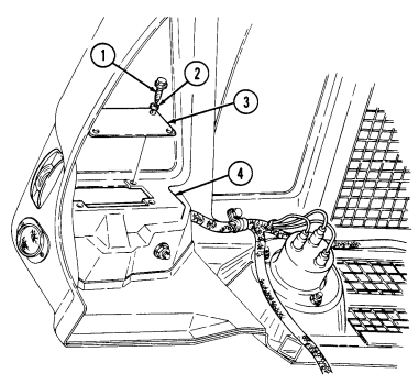
4-55. Side Marker Light Assembly Replacement (Cont'D)
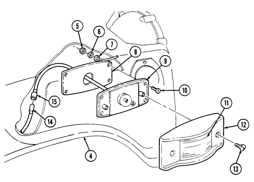
FOLLOW-ON TASKS: - Connect battery ground cable (para. 4-73).
- Lower and secure hood (front side marker only) (TM 9-2320-280-10). · Check side marker light for proper operation (TM 9-2320-280-10).
4-56. Rear Composite Light Assembly Replacement
This task covers:
a. Removal b. Installation
INITIAL SETUP: Tools General mechanic's tool kit: automotive (Appendix B, Item 1) Manual References TM 9-2320-280-10 TM 9-2320-280-24P Materials/Parts Two lockwashers (Appendix G, Item 135) Equipment Condition Battery ground cable disconnect (para. 4-73).
Prior to removal, tag leads for installation.
a. Removal 1. Remove two capscrews (3), washers (4), ground 95B (5), and ground strap (6) from housing (17).
- Remove two capscrews (15), lockwashers (16), and pull shield (1) away from "D" beam (14).
Discard lockwashers (16).
- Remove screw (2), nut (12) and clamp (11) from shield (1). 4. Disconnect leads 21 (7), 23 (8), 24 (9), and 22-461 (10) from body harness (13). 5. Remove composite light (18) from housing (17).
B. Installation
- Install composite light (18) on housing (17). 2. Connect leads 21 (7), 23 (8), 24 (9), and 22-461 (10) to body harness (13). 3. Install clamp (11) on shield (1) with screw (2) and nut (12). 4. Install shield (1) on "D" beam (14) with two capscrews (15) and lockwashers (16). 5. Install ground strap (6) and ground 95B (5) on housing (17) with two washers (4) and capscrews (3).
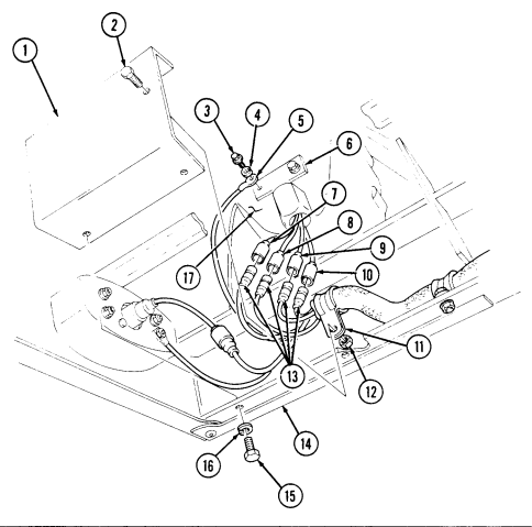
4-56. REAR COMPOSITE LIGHT ASSEMBLY REPLACEMENT (Cont'd)
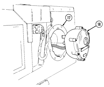
FOLLOW-ON TASKS: - Connect battery ground cable (para. 4-73).
- • - • Check rear composite light for proper operation (TM 9-2320-280-10).
4-57. Rear Composite Light Lamp Replacement
This task covers: INITIAL SETUP: Tools General mechanic's tool kit: automotive (Appendix B, Item 1) Materials/Parts O-ring (Appendix G, Item 221) Adhesive sealant (Appendix C, Item 10)
a. Removal b. Installation
Manual References TM 9-2320-280-10 TM 9-2320-280-24P Equipment Condition Battery ground cable disconnect (para. 4-73).
a. Removal 1. Loosen six retaining screws (3) and remove composite light door (4) and O-ring (5) from composite light (1). Discard O-ring (5).
- Remove lamp (2). 3. Clean mating surface on light door (4) and composite light (1). Remove sealant.
b. Installation 1. Install lamp (2).
To prevent moisture from entering light assembly, tighten all screws evenly.
- Install O-ring (5) and composite light door (4) on composite light (1) with six screws (3). 3. Apply a thin coat of sealant to seam between composite light (1) and composite light door (4).
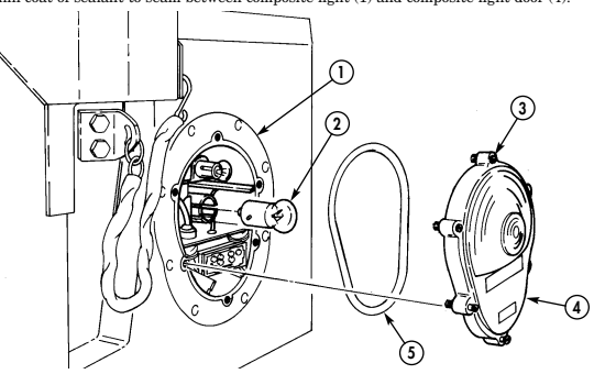
FOLLOW-ON TASKS: - Connect battery ground cable (para. 4-73).
- Check front composite light for proper operation (TM 9-2320-280-10).
4-58. Headlight Beam Selector Switch And Bracket Replacement
This task covers: INITIAL SETUP:
Tools
General mechanic's tool kit: automotive (Appendix B, Item 1) Riveter tool kit (Appendix B, Item 139) Materials/Parts Three assembled washer screws (Appendix G, Item 281) a. Removal a. Removal b. Installation Manual References TM 9-2320-280-10 TM 9-2320-280-24P Equipment Condition Battery ground cables disconnected (para. 4-73).
- Prior to removal, tag leads for installation.
- Deleted. b. Installation 1. Deleted. 2. Connect leads 16A (2), 17A (1), and 18A (10) to switch (3). 3. Install switch (3) and shield (5) on bracket (4) with three assembled washer screws (7).
- Pull back floor insulation for access to beam selector switch and bracket.
-
Remove three assembled washer screws (7), switch (3), and shield (5) from bracket (4). Discard assembled washer screws (7).
-
Disconnect leads 16A (2), 17A (1), and 18A (10) from switch (3).
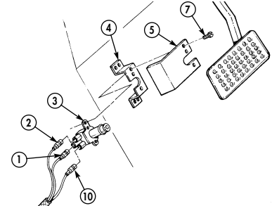
FOLLOW-ON TASKS: - Connect battery ground cables (para. 4-73).
- Check headlight beam selection switch for proper operation (TM 9-2320-280-10).
4-59. Main Light Switch Replacement
This task covers: INITIAL SETUP:
a. Removal b. Installation
| Tools | Manual References |
|---|---|
| General mechanic's tool kit: | TM 9-2320-280-10 |
| automotive (Appendix B, Item 1) | TM 9-2320-280-24P |
| Materials/Parts | Equipment Condition |
| O-ring (Appendix G, Item 220) Adhesive sealant (Appendix C, Item 10) | Battery ground cable disconnect (para. 4-73). |
a. Removal 1. Remove cannon plug (1) from main light switch (8). 2. Remove screw (6), lockwasher (5), top single position lever (4), and washer (7) from switch (8).
Discard lockwasher (5).
Lower right lever must be raised to remove screw.
- Remove four screws (3) from switch (8) and instrument panel (2). 4. Remove switch (8) from behind instrument panel (2).
b. Installation 1. With single position lever shaft (9) at top of switch (8), install switch (8) into hole in instrument panel (2) with four screws (3).
- Install washer (7) and top single position lever (4) to switch (8) with lockwasher (5) and screw (6). 3. Install cannon plug (1) to rear of switch (8).
4-59. Main Light Switch Replacement (Cont'D)
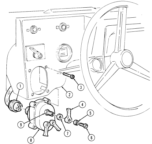
FOLLOW ON TASKS: - • Connect battery ground cable (para. 4-73).
- • - • - • Check main light switch for proper operation (TM 9-2320-280-10).
4-60. Stoplight Switch (11663279) Maintenance
This task covers: a. Removal c. Adjustment b. Installation INITIAL SETUP: Applicable Models All vehicles except: M997A2, M1025A2, M1035A2, M1043A2, M1045A2, M1097A2 Tools General mechanic's tool kit: automotive (Appendix B, Item 1) Test Equipment Multimeter (Appendix B, Item 166) Materials/Parts Push on nut (Appendix G, Item 226) Manual References TM 9-2320-280-10 TM 9-2320-280-24P Equipment Condition Battery ground cable disconnected (para. 4-73).
Prior to removal, tag leads for installation.
a. Removal 1. Remove push on nut (10) from rod connecting switch arm (5) and brake pedal arm (9).
Discard push on nut (10).
-
Remove two nuts (6), washers (1), capscrews (2), washers (1), and stoplight switch (3) from support (4).
-
Disconnect leads 75A (7) and 75B (8) from stoplight switch (3).
b. Installation 1. Install stoplight switch (3) on support (4) with two washers (1), capscrews (2), washers (1), and nuts (6).
- Install switch arm (5) into brake pedal arm (9) with push on nut (10). 3. Connect leads 75B (8) and 75A (7) to stoplight switch (3). 4. Adjust stoplight switch (3) (para. 4-60c).
C. Adjustment
-
Disconnect leads 75A (7) and 75B (8) from stoplight switch (3) and connect multimeter to leads on stoplight switch (3) to check continuity. Multimeter should indicate open. Depress brake pedal, multimeter should indicate continuity within approximately 1/2 in. (12 mm) of pedal travel. If not, go to step 2.
-
Loosen two capscrews (2) to allow movement of stoplight switch (3). 3. Position stoplight switch (3) so that continuity is present when installed. Slide stoplight switch forward until no continuity (open) is indicated (approximately 1/8 to 1/4 in. (3 to 6 mm).
-
Tighten two capscrews (2). 5. Connect leads 75A (7) and 75B (8) to stoplight switch (3). 6. Connect battery ground cable (para. 4-73). 7. Turn selector lever to service drive; stoplights should not illuminate. Depress brake pedal; stoplights should illuminate within 1/2 in. (12 mm) of pedal travel.
4-60. STOPLIGHT SWITCH (11663279) MAINTENANCE (Cont'd)
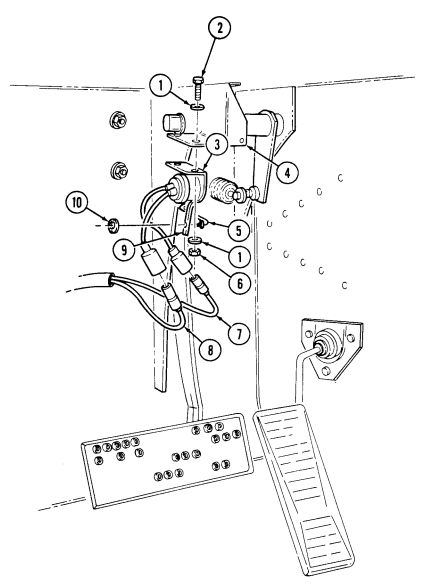
4-61. Stoplight Switch (Rcsk 17810) Maintenance
This task covers: a. Removal c. Adjustment b. Installation
Initial Setup:
Applicable Models M997A2, M1025A2, M1035A2, M1043A2, M1045A2, M1097A2, M1123 Tools General mechanic's tool kit: automotive (Appendix B, Item 1) Test Equipment Multimeter (Appendix B, Item 166)
Materials/Parts
Two push on nuts (Appendix G, Item 226) Two assembled locknuts (Appendix G, Item 130) Sealing compound (Appendix C, Item 45) Equipment Condition Battery ground cables disconnected (para. 4-73).
a. Removal
B. Installation
- Connect leads 75A (1), 75B (16), and connector 810A/810B (15) to stoplight switch leads (2).
C. Adjustment
-
Disconnect leads 75A (1), 75B (16), and connector 810A/810B (15) from stoplight switch leads (2) and connect multimeter to leads on stoplight switch (3) to check continuity. Multimeter should indicate open. Depress brake pedal; multimeter should indicate continuity within approximately 1/4 in. (6 mm) of pedal travel. If not, go to step 2.
-
Loosen two capscrews (5) to allow movement of stoplight switch (3). 3. Position stoplight switch (3) so that continuity is present when installed. Slide stoplight switch forward until no continuity (open) is indicated (approximately 1/4 in. (6 mm)).
-
Tighten two capscrews (5).
-
Turn selector lever to service drive; stoplights should not illuminate. Depress brake pedal; stoplights should illuminate within 1/4 in. (6 mm) of pedal travel.
4-100 Change 3
Prior to removal, tag leads for installation.
-
Disconnect leads 75A (1), 75B (16), and connector 810A/810B (15) from stoplight switch leads (2). 2. Remove push on nut (14), stoplight switch arm (13), and washer (12) from actuating rod (10). Discard push on nut (14).
-
Remove two assembled locknuts (6), washers (4), capscrews (5), washers (4), and stoplight switch (3) from mounting bracket (7). Discard assembled locknuts (6).
-
Remove push on nut (9), actuating rod (10), and washer (11) from brake pedal (8). Discard push on nut (9).
-
Install washer (11) and actuating rod (10) on brake pedal (8) with push on nut (9). 2. Install washer (12) and stoplight switch arm (13) on actuating rod (10) with push on nut (14). 3. Install stoplight switch (3) on mounting bracket (7) with two washers (4), capscrews (5), washers (4), and assembled locknuts (6).
-
Connect leads 75B (1), 75A (16), and connector 810A/810B (15) to stoplight switch leads (2). 6. Connect battery ground cables (para. 4-73).
4-61. Stoplight Switch (Rcsk 17810) Maintenance (Cont'D)
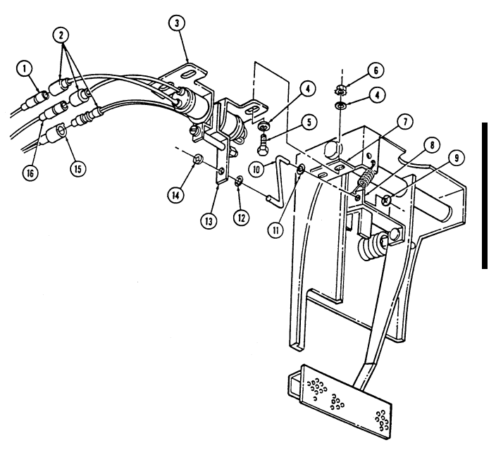
4-62. Directional Signal Flasher Replacement
This task covers: INITIAL SETUP: Tools General mechanic's tool kit: automotive (Appendix B, Item 1)
a. Removal b. Installation
| Manual References |
|---|
| TM 9-2320-280-10 |
TM 9-2320-280-24P Materials/Parts Silicone compound (Appendix C, Item 48) Equipment Condition Battery ground cable disconnected (para. 4-73).
The flasher is located under the instrument panel to the left of the steering column.
a. Removal 1. Remove cannon plug (1) from main light switch (2). 2. Remove connector plug (7) from flasher (5). 3. Remove two nuts (3), screws (6), and flasher (5) from instrument panel (8).
b. Installation 1. Install flasher (5) on instrument panel (8) with two screws (6) and nuts (3). 2. Apply silicone compound to threads of connector plug (7). Install connector plug (7) on flasher (5). 3. Connect cannon plug (1) to main light switch (2).
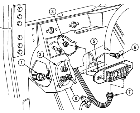
FOLLOW-ON TASKS: - Connect battery ground cable (para. 4-73).
- Check directional signal flasher for proper operation (TM 9-2320-280-10).
4-102 Change 3
4 - 6 3 . Directional Signal Control Indicator Lamp Replacement
This task covers: a. Removal b. Installation INITIAL SETUP: Tools General mechanic's tool kit: automotive (Appendix B, Item 1) Equipment Condition Battery ground cable disconnected (para. 4-73).
Manual References TM 9-2320-280-10 TM 9-2320-280-24P a. Removal 1. Push turn signal indicator lever (1) in the four-way flasher position (TM 9-2320-280-10). 2. Remove light lens (3) from directional control unit (4). 3. Remove lamp (2) from directional control unit (4).
b. Installation 1. Install lamp (2) into directional control unit (4).
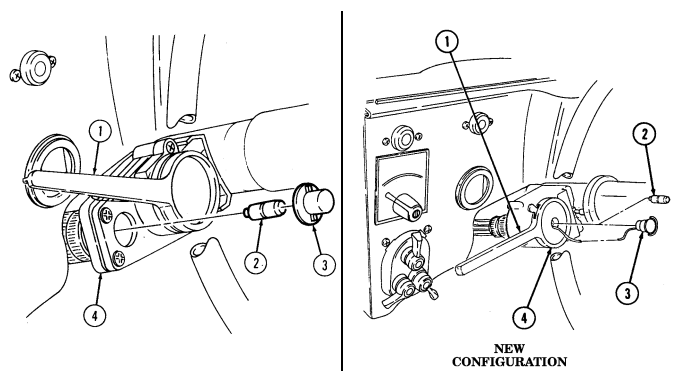 2. Install light lens (3) into directional control unit (4).
FOLLOW-ON TASKS: - Connect battery ground cable (para. 4-73).
- Check directional signal control lamp for proper operation (TM 9-2320-280-10).
4-64. Directional Signal Control (12339312-1) Maintenance
This task covers: b. Cleaning
Initial Setup:
Applicable Models All vehicles except: M997A2, M1025A2, M1035A2, M1043A2, M1045A2, M1097A2, M1123 Tools General mechanic's tool kit: automotive (Appendix B, Item 1) Materials/Parts Cleaning and lubricating compound (Appendix C, Item 16) a. Removal c. Installation Manual References TM 9-2320-280-10 TM 9-2320-280-24P Equipment Condition Battery ground cable disconnected (para. 4-73).
The directional signal control for this application is no longer available. For replacement of a defective directional signal control, the procedures and part number for the A2 application should be used (para. 4-65).
a. Removal 1. Loosen connector nut (4) and remove connector plug (5) from directional signal control (3). 2. Remove four screws (2) and directional signal control (3) from clamp (1).
b. Cleaning
Clean the signal control before replacing it. After cleaning, install and try again before replacing.
- Remove four screws (7) and signal arm plate (6) from signal control (3).
Do not sand contacts with sandpaper or an emery board which removes the protective coating that fights corrosion. Damage to the switch will result.
The cleaner has an alcohol base that dries quickly.
- Spray signal control contacts (8) with cleaning compound. 3. Install signal arm plate (6) on signal control (3) with four screws (7).
c. Installation 1. Install directional signal control (3) on clamp (1) with four screws (2). 2. Install connector plug (5) on directional signal control (3) and tighten connector nut (4).
4-64. Directional Signal Control (12339312-1) Maintenance (Cont'D)
l
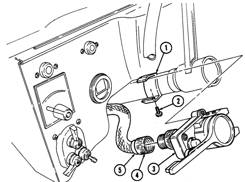
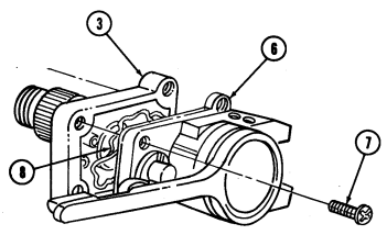
FOLLOW-ON TASKS: - Connect battery ground cable (para. 4-73).
· Check directional signal control for proper operation (TM 9-2320-280-10).
4 - 6 5 . Directional Signal Control Replacement
This task covers: INITIAL SETUP: Applicable Models M997A2, M1025A2, M1035A2, M1043A2, M1045A2, M1097A2, M1123 Tools General mechanic's tool kit: automotive (Appendix B, Item 1)
a. Removal b. Installation
| Equipment Condition |
|---|
| Manual References |
|---|
| TM 9-2320-280-10 |
| TM 9-2320-280-24P |
Battery ground cables disconnected (para. 4-73).
a. Removal 1. Loosen connector nut (6) and remove connector plug (7) from directional signal control (4). 2. Remove four screws (2) and directional signal control (4) from bracket (1).
b. Installation 1. Place lever (5) in HAZARD position. 2. Install directional signal control (4) on bracket (1) with four screws (2). Do not tighten screws (2).
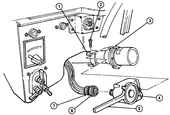 3 . Rotate steering wheel ensuring pin (3) mates with directional signal control (4) and tighten screws (2)
to 22-26 lb-in. (2.5-2.9 N•m ) .
- Install connector plug (7) on directional signal control (4) and tighten connector nut (6).
FOLLOW-ON TASKS: - Connect battery ground cables (para. 4-73).
- Check directional signal control lamp for proper operation (TM 9-2320-280-10).
4 - 1 0 6 Change 2
4 - 6 6 . Directional Signal Control Cancelling Ring Replacement
| This task covers: |
|---|
| INITIAL SETUP: | |
|---|---|
| Tools | Manual References |
| General mechanic's tool kit: | TM 9-2320-280-10 |
| automotive (Appendix B, Item 1) | TM 9-2320-280-24P |
| Materials/Parts | Equipment Condition |
| O-ring (Appendix G, Item 221) | Battery ground cable disconnect (para. 4-73). |
| Adhesive sealant (Appendix C, Item 10) |
a. Removal b. Installation
a. Removal Remove three screws (5) and cancelling ring (4) from steering wheel (6).
b. Installation
Cancelling ring pin must be positioned 90° ± 5° from directional signal control. Ensure front wheels of vehicle point straight ahead. Failure to position pin properly could cause loss of steering, with injury to personnel or damage to equipment.
- Install cancelling ring (4) on steering wheel (6) with pin (2) 90° ± 5° from directional signal control (1). 2. Rotate steering wheel (6), ensuring pin (2) mates with directional signal control (1) and secure cancelling ring (4) on steering wheel (6) with three screws (5).
Note Gauge posts found on new cancelling rings are there to ensure proper
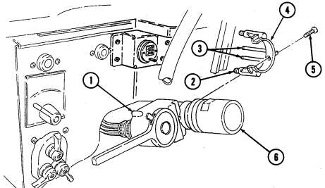 installation only. Gauge posts must be removed after installation of cancelling ring to permit proper operation of directional signal control.
- Cut gauge posts (3) off within 1/4 in. (6 mm) of base.
FOLLOW-ON TASK: Check directional signal control for proper operation (TM 9-2320-280-10).
4-67. Service Headlight And Blackout Drive Light Electrical Connector And Grommet Replacement
This task covers: INITIAL SETUP: General mechanic's tool kit: Service headlight lamp removed (para. 4-48).
automotive (Appendix B, Item 1) Manual References TM 9-2320-280-24P a. Removal b. Installation Tools Equipment Condition
The procedure to remove and install the connector and grommet from service headlight and blackout drive light is basically the same. The following procedure is for the service headlight.
a. Removal Remove connector (3) from grommet (1) and remove grommet (1) from headlight housing (2).
b. Installation Install grommet (1) to headlight housing (2) and install connector (3) to grommet (1).
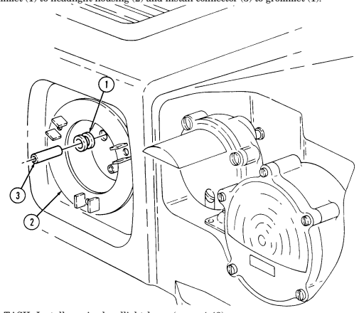
FOLLOW-ON TASK: Install service headlight lamp (para. 4-48).
4-68. Backup Light Lamp Replacement
This task covers: INITIAL SETUP: Applicable Models M1035, M1035A1, M1035A2 Tools General mechanic's tool kit: automotive (Appendix B, Item 1) Materials Parts Gasket (Appendix G, Item 47)
a. Removal b. Installation
| Manual References |
|---|
| TM 9-2320-280-10 |
TM 9-2320-280-10 TM 9-2320-280-24P Equipment Condition Battery ground cable disconnected (para. 4-73).
a. Removal 1. Remove two screws (5), bezel (4), lens (3), and gasket (2) from housing (1). Discard gasket (2). 2. Remove lamp (6) from housing (1).
b. Installation 1. Install lamp (6) in housing (1). 2. Install gasket (2), lens (3), and bezel (4) on housing (1) with two screws (5).
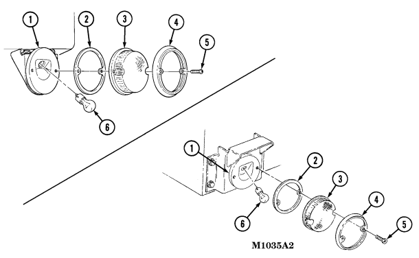
FOLLOW-ON TASKS: - Connect battery ground cable (para. 4-73).
- Check backup light for proper operation (TM 9-2320-280-10).
4-69. Backup Light Assembly Replacement
This task covers: INITIAL SETUP: Applicable Models M1035, M1035A1, M1035A2 Tools General mechanic's tool kit: automotive (Appendix B, Item 1) Materials Parts Two lockwashers (Appendix G, Item 139) Tiedown strap (Appendix G, Item 310)
a. Removal b. Installation
Manual References TM 9-2320-280-10 TM 9-2320-280-24P Equipment Condition Battery ground cable disconnected (para. 4-73).
a. Removal
- Perform steps 1 and 2 for M1035 and M1035A1 vehicles. - Perform steps 3 through 5 for M1035A2 vehicle.
- Disconnect lead 467F (1) from lamp assembly (3). 2. Remove two nuts (6), lockwashers (5), lead 95H (4), and lamp assembly (3) from bracket (2).
Discard lockwashers (5).
- Remove tiedown strap (11) and disconnect leads 467F (1) and 95H (4) from body harness leads (10).
Discard tiedown strap (11).
- Remove capscrew (8) and clamp (9) from body (12). 5. Remove two nuts (6), lockwashers (5), lead 95H (4), and lamp assembly (3) from bracket (7).
Discard lockwashers (5).
b. Installation
- Perform steps 1 through 3 for M1035A2 vehicle. - Perform steps 4 and 5 for M1035 and M1035A1 vehicles.
- Install lamp assembly (3) and lead 95H (4) on bracket (7) with two lockwashers (5) and nuts (6). 2. Connect leads 467F (1) and 95H (4) to body harness leads (10) and install tiedown strap (11). 3. Install clamp (9) on body (12) with capscrew (8). 4. Install lamp assembly (3) and lead 95H (4) on bracket (2) with two lockwashers (5) and nuts (6). 5. Connect lead 467F (1) to lamp assembly (3).
4-69. Backup Light Assembly Replacement (Cont'D)
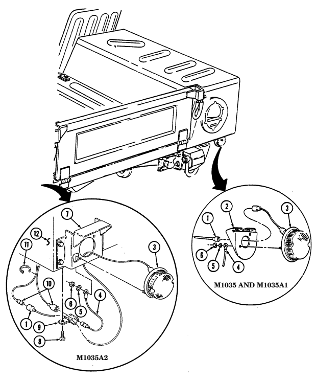
FOLLOW-ON TASKS: - Connect battery ground cable (para. 4-73).
- Check backup light for proper operation (TM 9-2320-280-10).
4-70. Backup Light Bracket Replacement
This task covers: INITIAL SETUP: Applicable Models M1035, M1035A1, M1035A2 Tools General mechanic's tool kit: automotive (Appendix B, Item 1) Materials Parts Two lockwashers (Appendix G, Item 133) a. Removal b. Installation Manual References TM 9-2320-280-24P Equipment Condition Backup light assembly removed (para. 4-69).
M1035A2 vehicles are equipped with four nuts, eight washers, and four capscrews.
a. Removal Remove two nuts (5), lockwashers (4), washers (3), capscrews (1) and bracket (6) from "D" beam (2). Discard lockwashers (4).
b. Installation Install bracket (6) on "D" beam (2) with two capscrews (1), washers (3), lockwashers (4), and nuts (5).
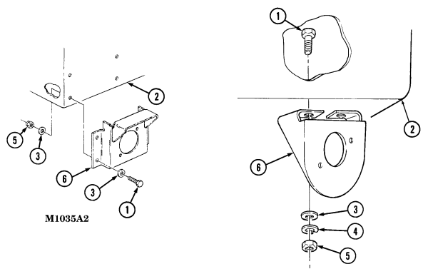
FOLLOW-ON TASK: Install backup light assembly (para. 4-69).
Section Vi. Battery System Maintenance
| INITIAL SETUP: | |
|---|---|
| Applicable Models | Manual References |
| M997A2, M1025A2, M1035A2, M1043A2, | TM 9-2320-280-10 |
| M1045A2, M1097A2, M1123 | TM 9-2320-280-24P |
| Equipment Condition | Tools |
| Battery ground cables disconnected (para. 4-73). | General mechanic's tool kit: |
| automotive (Appendix B, Item 1) | |
| a. Removal | |
| 1. | Loosen connector nut (6) and remove connector plug (7) from directional signal control (4). |
| 2. | Remove four screws (2) and directional signal control (4) from bracket (1). |
| b. Installation | |
| 1. | Place lever (5) in HAZARD position. |
| 2. | Install directional signal control (4) on bracket (1) with four screws (2). Do not tighten screws (2). |
| 3 . | Rotate steering wheel ensuring pin (3) mates with directional signal control (4) and tighten screws (2) |
| to 22-26 lb-in. (2.5-2.9 N•m ) . | |
| 4. | Install connector plug (7) on directional signal control (4) and tighten connector nut (6). |
4 - 7 1 . B At T E Ry System Maintenance Task Summary 4-72. Battery Cable Terminal Clamp Replacement
This task covers: INITIAL SETUP: Tools General mechanic's tool kit: automotive (Appendix B, Item 1) Materials/Parts Lubricating oil (Appendix C, Item 33) Manual References TM 9-2320-280-10 TM 9-2320-280-24P
A. Removal B. Installation Equipment Condition
Battery box cover removed (para. 10-35).
General Safety Instructions
Wear safety goggles and rubber gloves and do not smoke when performing battery maintenance.
Remove all jewelry.
When removing battery cable clamps, disconnect ground cable first.
Battery acid (electrolyte) is extremely harmful. Always wear safety goggles and rubber gloves, and do not smoke when performing battery maintenance. Severe injury will result if acid contacts eyes or skin.
Remove ail jewelry such as rings, dogtags, bracelets, etc. If jewelry or disconnected battery ground cable contacts battery terminal, a direct short can result, causing instant heating of tools, severe injury to personnel, or damage to equipment.
When removing battery cable clamps, disconnect ground cable first.
Do not allow tools to come in contact with vehicle when discomecting cable clamps. A direct short can result, causing instant heating of tools, tool damage, battery damage, or battery explosion.
a. Removal
The procedure for removing and installing all four battery cable terminal clamps are basically the same. This procedure covers one battery cable terminal clamp.
-
Remove cap (4) from battery terminal boot (8).
-
Clean lubricating oil from battery terminal boot (8). 3. Loosen screw (6), nut (7), and remove terminal clamp (3) from terminal post (9). 4. Remove screw (2) and nut (5) from cable (1) and terminal clamp (3). 5. Remove cable (1) from terminal clamp (3) and battery terminal boot (8).
-
Remove terminal clamp (3) from battery terminal boot (8).
B. Installation
-
Push battery terminal boot (8) onto cable (1).
-
Place terminal clamp (3) into battery terminal boot (8) and install cable (1) on terminal clamp (3) with screw (2) and nut (5).
-
Apply lubricating oil to battery post pad (10). Do not allow lubricating oil to coat terminal post (9). 4. Secure terminal clamp (3) to terminal post (9) by tightening screw (6) and nut (7). 5. Apply lubricating oil to terminal clamp (3). 6. Install cap (4) to battery terminal boot (8).
4-72. Battery Cable Terminal Clamp Replacement (Cont'D)
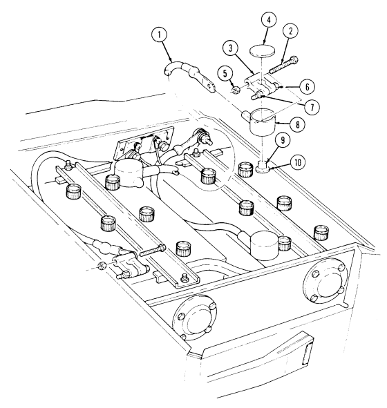
FOLLOW-ON TASK: Install battery box cover (para. 10-35).
4-73. Battery Cable Maintenance
This task covers: c. Ground Cables Reconnection h. Positive Cable Removal d. Ground Cable Removal i. Positive Cable Installation e. Ground Cable Installation
Initial Setup:
Tools General mechanic's tool kit: automotive (Appendix B, Item 1)
Materials/Parts
Lockwasher (Appendix G, Item 141) Lockwasher (Appendix G, Item 148) Lockwasher (Appendix G, Item 150) Sodium bicarbonate (Appendix C, Item 49) Lubricating oil (Appendix C, Item 33) Silicone compound (Appendix C, Item 48)
Manual References Tm 9-2320-280-24P
a. Cleaning and Inspection f. Interconnecting Cable Removal b. Ground Cables Disconnection g. Interconnecting Cable Installation
Equipment Condition
Battery box cover removed (para. 10-35).
General Safety Instructions
-
Wear safety goggles and rubber gloves and do not smoke when performing battery maintenance.
-
Remove all jewelry. - When removing battery cables, disconnect ground cable first. Ensure all switches are in OFF position before disconnecting.
-
Battery acid (electrolyte) is extremely harmful. Always wear safety goggles and rubber gloves, and do not smoke when performing battery maintenance. Severe injury will result if acid contacts eyes or skin.
-
Remove all jewelry such as rings, dogtags, bracelets, etc. If jewelry or disconnected battery ground cable contacts battery terminal, a direct short can result, causing instant heating of tools, severe injury to personnel, or damage to equipment.
-
Always disconnect both ground cables when performing battery maintenance on the "A2" series vehicles. The "A2" series vehicles have a 12 volt cable connected to the positive terminal, which keeps the electrical system charged when only one ground cable is disconnected. Failure to do this may cause injury to personnel, or damage to equipment.
-
When removing battery cable clamps, disconnect both ground cables first. Ensure all switches are in OFF position before disconnecting. Do not allow tools to come in contact with vehicle when disconnecting cable clamps. A direct short can result, causing instant heating of tools, tool damage, battery damage, or battery explosion.
-
Secure all cables to head side of mounting capscrews. - Use this procedure for disconnecting all battery cables. - The following procedure covers disconnection and connection of the ground cable.
A. Cleaning And Inspection
- Inspect cables (1), (2), and (11) for corrosion and cracks. 2. Remove defective cables (1), (2), and (11), or clean with wire brush and baking soda solution.
4-73. Battery Cable Maintenance (Cont'D)
b. Ground Cables Disconnection
Perform steps 1 through 6 for M997A2, M1025A2, M1035A2, M1043A2, M1045A2, and M1097A2 vehicles only. Perform step 7 for all other vehicles.
-
Remove nut (12), leads (13) and (14), screw (16), and ground cable (1) from terminal clamp (15). 2. Remove cap (5) from battery terminal boot (8). 3. Clean lubricating oil from battery terminal boot (8).
-
Loosen nut (7) and remove terminal clamp (4) from terminal (9).
-
Remove nut (3) and screw (6) from cable (2) and terminal clamp (4).
-
Remove cable (2) from terminal clamp (4) and battery terminal boot (8). 7. Remove nut (12), screw (16), and ground cable (1) from terminal clamp (15).
c. Ground Cables Reconnection
Perform steps 1 through 6 for M997A2, M1025A2, M1035A2, M1043A2, M1045A2, and M1097A2 vehicles only. Perform step 7 for all other vehicles.
-
Push battery terminal boot (8) onto cable (2) and secure cable (2) to terminal clamp (4) with screw (6) and nut (3).
-
Apply a 1/16 in. (1.6mm) bead of lubricating oil to battery post pad (10). Do not allow oil to coat terminal post (9).
-
Install terminal clamp (4) to terminal (9) and tighten nut (7).
-
Fill battery terminal boot (8) with lubricating oil. 5. Install cap (5) to battery terminal boot (8).
-
Install ground cable (1) and leads (14) and (13) on terminal clamp (15) with screw (16) and nut (12).
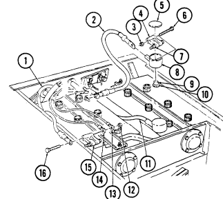 7. Install ground cable (1) on terminal clamp (15) with screw (16) and nut (12).
4-73. Battery Cable Maintenance (Cont'D)
d. Ground Cable Removal
Perform step 1 for M997A2, M1025A22, M1035A2, M1043A2, M1045A2, and M1097A2 vehicles only. Perform step 2 for all other vehicles.
-
Remove nut (5), leads (6) and (7), screw (9), and ground cable (4) from terminal clamp (8).
-
Remove nut (5), screw (9), and ground cable (4) from terminal clamp. 3. Remove capscrew (3), lockwasher (2), and ground cable (4) from shunt (1).
E. Ground Cable Installation
- Position ground cable (4) in approximate mounting location and install ground cable (4) to shunt (1) with lockwasher (2) and capscrew (3).
Perform step 2 for M997A2, M1025A2, M1035A2, M1043A2, M1045A2, and M1097A2 vehicles only. Perform step 3 for all other vehicles.
- Install ground cable (4) on terminal clamp (8) with screw (9), leads (7) and (6), and nut (5).
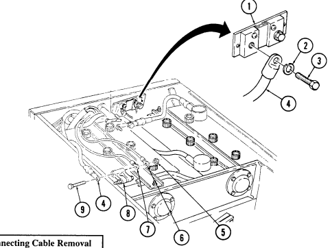 3. Install ground cable (4) on terminal clamp (8) with screw (9) and nut (5).
NOTE All vehicles except M997A2, M1025A2, M1035A2, M1043A2, M1045A2, and M1097A2 vehicles have two caps and boots.
-
Remove cap (19) from battery terminal boot (20).
-
Clean lubricating oil from battery terminal boot (20).
4-73. Battery Cable Maintenance (Cont'D)
Perform steps 3 through 5 for M997A2, M1025A2, M1035A2, M1043A2, M1045A2, and M1097A2 vehicles only. Perform steps 6 and 7 for all other vehicles.
-
Loosen two nuts (12) and remove terminal clamps (17) from terminals (11).
-
Remove nut (18), capscrew (14), cable (13), leads (15) and cable (16) from terminal clamp (17). 5. Remove nut (18) and screw (14) from cable (16) and terminal clamps (17). 6. Loosen two nuts (12) and remove terminal clamps (17) from terminals (11).
-
Remove two screws (14), nuts (18), and cable (16) from terminal clamps (17).
-
Remove cable (16) from terminal clamps (17) and battery terminal boot (20).
g. Interconnecting Cable Installation
All vehicles except M997A2, M1025A2, M1035A2, M1043A2, M1045A2, and M1097A2 vehicles have two caps and boots.
-
Push battery terminal boot (20) onto cable (16) and install cable (16) on terminal clamp (17) with screw (14) and nut (18).
-
Apply a 1/16 in. (1.6mm) bead of lubricating oil to battery post pads (10). DO not allow oil to coat terminal posts (11).
Perform steps 3 and 4 for M997A2, M1025A2, M1035A2, M1043A2, M1045A2, and M1097A2 vehicles only. Perform steps 5 and 6 for all other vehicles.
-
Install cable (16), leads (15), and cable (13) to terminal clamp (17) with screw (14) and nut (18).
-
Install two terminal clamps (17) on terminals (11) and tighten nuts (12).
-
Install cable (16) on terminal clamp (17) with capscrew (14) and nut (18).
-
Install two terminal clamps (17) on terminal posts (11) and tighten nuts (12). 7. Fill battery terminal boot (20) with lubricating oil. 8. Install cap (19) to battery terminal boot (20).
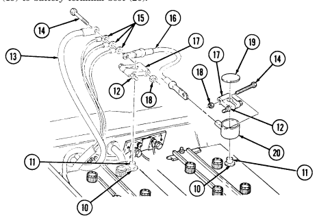
4-73. Battery Cable Maintenance (Cont'D) H. Positive Cable Removal
-
Disconnect ground cable (para. 4-73.b).
-
Remove cap (8) from battery terminal boot (12). 3. Clean lubricating oil from battery terminal boot (12). 4. Loosen nut (11) and remove terminal clamp (7) from terminal (14).
-
Remove screw (6), nut (9), and cable (2) from terminal clamp (7) and battery terminal boot (12).
Perform step 6 for M997A2, M1025A2, M1035A2, M1043A2, M1045A2, and M1097A2 vehicles only. Perform step 7 for all other vehicles.
-
Remove nut (5), lockwasher (4), washer (3), and battery positive cable (2) from buss bar (1). Discard lockwasher (4).
-
Remove nut (5), lockwasher (4), washer (3), slave receptacle positive cable (15), and battery positive cable (2) from power stud (16). Discard lockwasher (4).
i. Positive Cable Installation
Perform step 1 for M997A2, M1025A2, M1035A2, M1043A2, M1045A2, and M1097A2 vehicles only Perform step 2 for all other vehicles.
Install positive battery cable (2) on buss bar (1) with washer (3), lockwasher (4), and nut (5). Apply silicone compound on cable (15) so that all exposed metallic surfaces are coated.
Install positive battery cable (2) and slave receptacle positive cable (15) on power stud (16) with washer (3), lockwasher (4), and nut (5). Tighten nut (5) to 26 lb-ft (35 N.m). Push battery terminal boot (12) onto cable (2) and install cable (2) on terminal clamp (7) with screw (6) and nut (9).
Apply a 1/16 in. (1.6mm) bead of lubricating oil to battery post pad (13). Do not allow oil to coat terminal post (14). Secure terminal clamp (7) to terminal post (14) and tighten nut (11).
Fill battery terminal boot (12) with lubricating oil. Install cap (8) on battery terminal boot (12).
Connect battery ground cable (para. 4-73.c).
4-73. Battery Cable Maintenance (Cont'D)
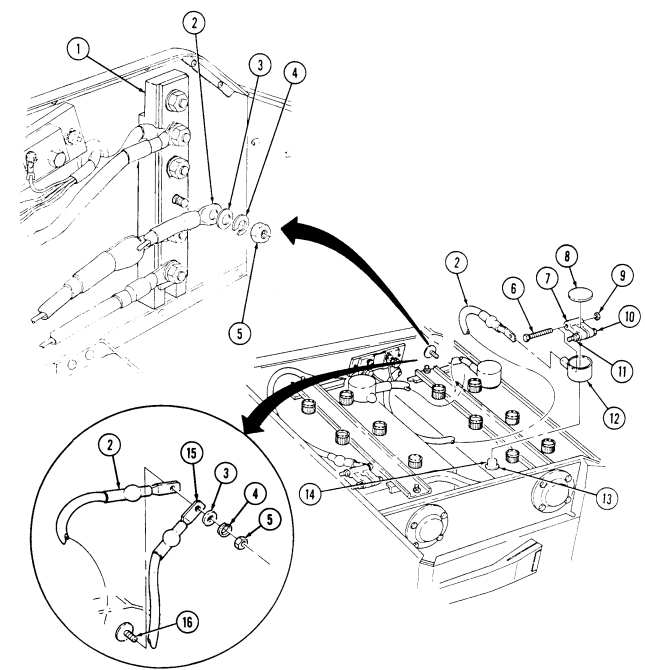
FOLLOW-ON TASK: Install battery box cover (para. 10-35).
4-74. Power Feed Through Stud Replacement
This task covers:
a. Removal b. Installation
| INITIAL SETUP: | |
|---|---|
| Applicable Models | Manual References |
| M1035, M1035A1, M1035A2 | TM 9-2320-280-10 |
| TM 9-2320-280-24P | |
| Tools | |
| General mechanic's tool kit: | Equipment Condition |
| automotive (Appendix B, Item 1) | Battery ground cable disconnected (para. 4-73). |
| Materials Parts |
A. Removal
- Remove nut (1), lockwasher (2), washer (3), leads 6B/6C (4), and starter cable (5), from stud (8).
Discard lockwasher (2).
Step 2 applies to all vehicles except M997A2, M1025A2, M1035A2, M1043A2, M1045A2, and M1097A2.
-
Remove nut (12), lockwasher (11), washer (10), and battery cables (9) from stud (8). Discard lockwasher (11).
-
Remove locknut (6) and stud (8) from battery box (7).
b. Installation 1. Install stud (8) on battery box (7) with locknut (6).
Step 2 applies to all vehicles except M997A2, M1025A2, M1035A2, M1043A2, M1045A2, and M1097A2 vehicles.
-
Connect battery cables (9) to stud (8) with washer (10), lockwasher (11), and nut (12). Tighten nut (12) to 26 lb-ft (35 N•m).
-
Install starter cable (5) and leads 6B/6C (4) to stud (8) with washer (3), lockwasher (2), and nut (1). Tighten nut (1) to 18-22 lb-ft (24-30 N•m).
-
Apply silicone compound to stud (8), cables (9) and (5), and leads (4), so that all exposed metallic surfaces are coated.
4-74. Power Feed Through Stud Replacement
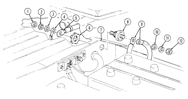
FOLLOW-ON TASK: - Install buss bar (para. 4-76).
M997A2, M1025A2, M1035A2, M1043A2, M1045A2, and M1097A2.
- Connect battery ground cables (para. 4-73).
4-75. 12 Volt Alternator Cable Replacement
This task covers: INITIAL SETUP: Applicable Models M997A2, M1025A2, M1035A2, M1043A2, M1045A2, M1097A2 Tools General mechanic's tool kit: automotive (Appendix B, Item 1)
Material/Parts
a. Removal b. Installation Manual References TM 9-2320-280-10 TM 9-2320-280-24P Equipment Condition
- Battery ground cables disconnected (para. 4-73). - Hood raised and secured (TM 9-2320-280-10). - Engine access cover removed (para. 10-15).
Two tiedown straps (Appendix G, Item 312)
Prior to removal, tag leads for installation.
A. Removal
- Slide back rubber boot (9) and remove nut (8), washer (7), and cable (1) from regulator (6). 2. Remove capscrew (3) securing clamp (4) and cable (1) to bracket (2). 3. Remove two tiedown straps (10) from cable (1). Discard tiedown straps (10). 4. Remove nut (15), screw (11), cable (1), leads (12), and cable (13) from terminal clamp(14) and
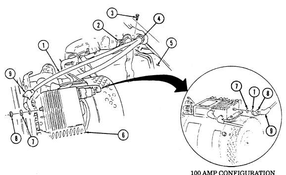
remove cable (1) from battery box (16) and engine (5).
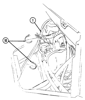
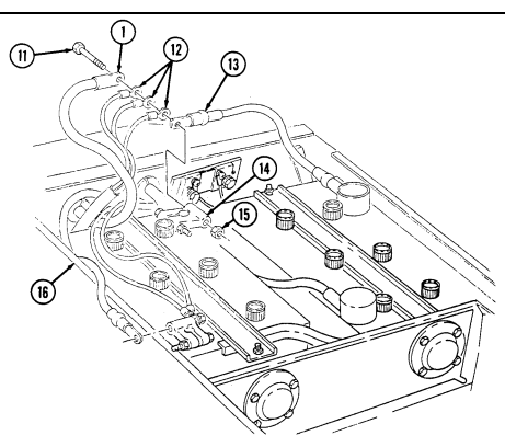
4-75. 12 VOLT ALTERNATOR CABLE REPLACEMENT (Cont'd)
4-75. 12 Volt Alternator Cable Replacement (Cont'D)
B. Installation
-
Position cable (1) in approximate mounting location on engine (5) and through hole in battery box (16).
-
Install cable (13), leads (12), and cable (1) on terminal clamp (14) with screw (11) and nut (15).
-
Install two tiedown straps (10) on cable (1).
-
Install cable (1) and clamp (4) on bracket (2) with capscrew (3).
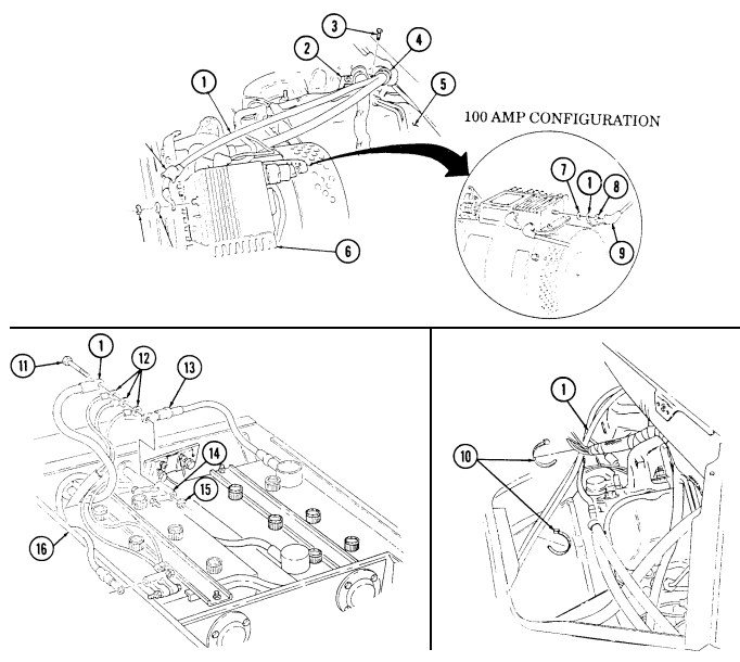 5. Install cable (1) on regulator (6) with washer (7) and nut (8). Tighten nut (8) to 18-22 lb-in.
2.0-2.5 N·m). lide rubber boot (9) over nut (8).
Lower and secure hood (TM 9-2320-280-10). Connect battery ground cables (para. 4-73). Install engine access cover (para. 10-15).
FOLLOW-ON TASKS:
4-76. Buss Bar Replacement
This task covers: INITIAL SETUP: Applicable Models M997A2, M1025A2, M1035A2, M1043A2, M1045A2, M1097A2 Tools General mechanic's tool kit: automotive (Appendix B, Item 1) a. Removal
a. Removal b. Installation
| Equipment Condition |
|---|
| Battery removed (para. 4-79). |
| Manual References |
|---|
| TM 9-2320-280-10 |
| TM 9-2320-280-24P |
-
Remove five nuts (9), lockwashers (8), and washers (7), engine harness cable (6), alternator cable (10), battery cable (11), umbilical power cable (12) (M1097A2 vehicles only), and slave receptacle cable (13) from buss bar (2). Discard lockwashers (8).
-
Remove nut (5), lockwasher (4), washer (3), and buss bar (2) from power feed through stud (1).
Discard lockwasher (4).
B. Installation
-
Install buss bar (2) to power feed through stud (1) with washer (3), lockwasher (4), and nut (5). 2. Install engine harness cable (6), alternator cable (10), battery cable (11), umbilical power cable (12) (M1097A2 vehicles only), and slave receptacle cable (13) on buss bar (2) with five washers (7), lockwashers (8), and nuts (9).
-
Apply silicone compound to buss bar (2), so that all exposed metallic surfaces are coated.
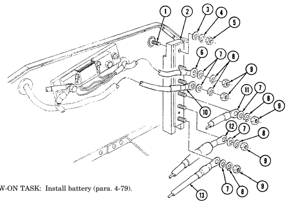
4-77. Starter Power Cables Replacement
This task covers: INITIAL SETUP: Tools General mechanic's tool kit: automotive (Appendix B, Item 1)
Materials/Parts
Two lockwashers (Appendix G, Item 133) Assembled locknut (Appendix G, Item 130) Lockwasher (Appendix G, Item 141) Lockwasher (Appendix G, Item 178) Lockwasher (Appendix G, Item 137) Two lockwashers (Appendix G, Item 150) Tiedown strap (Appendix G, Item 306) Adhesive sealant (Appendix C, Item 10)
A. Removal B. Installation
Manual References TM 9-2320-280-10 TM 9-2320-280-24P Equipment Condition
-
Battery ground cable disconnected (para. 4-73).
-
Raise and secure hood (TM 9-2320-280-10).
Prior to removal, tag all leads for installation.
A. Removal
-
Slide back rubber boot (1) on positive cable (3) for access to nut (8). Remove nut (8), lockwasher (9), washer (10), lead 6B/6C (11), and positive cable (3) from power stud (2). Discard lockwasher (9).
-
Remove nut (7), lockwasher (6), and ground cable (5) from ground stud (4). Discard lockwasher (6). 3. Remove screw (30), two clamps (32), positive cable (3), and ground cable (5) from starter (23) and remove clamps (32) from cables (3) and (5).
-
Remove nut (33), lockwasher (34), ground cable (5), lead 7C (36) (winch vehicles only), and STE/ICE-R lead 3C (35) from negative post (37) on starter (23). Discard lockwasher (34).
Perform step 5 for all vehicles except "A2" vehicle series vehicles. Perform steps 6 and 7 for M997A2, M1025A2, M1035A2, M1043A2, M1045A2, and M1097A2 vehicles only.
-
Remove nut (28), lockwasher (27), positive cable (3), positive accessory cable (26) (vehicles with winch or 200 amp alternator only), and STE/ICE-R leads 81A (25) and 81B (43) from positive post (24). Discard lockwasher (27)
-
Remove nut (28), lockwasher (27) and lead 81B (43) from positive post (24). Discard lockwasher (27). 7. Remove two nuts (44), lockwashers (45), washers (46), positive cable (48), and positive accessory cable (47) (vehicles with winch or 200 amp alternator only) from buss bar (49). Discard lockwasher (45).
-
Remove screw (38), clip (39), and leads 74A (41) and 74B (40) from solenoid (42).
Proceed to step 12 for all vehicles except M997, M997A1, and M997A2. Perform steps 9 through 11 for M997, M997A1 and M997A2 vehicles only.
- Remove nut (18), lockwasher (17), clamp (15), and compressor harness (16) from capscrew (14).
Discard lockwasher (17).
- Disconnect compressor harness lead (13) from compressor leads (12). 11. Remove assembled locknut (20), clamp (19), and compressor harness (16) from cable bracket screw (21). Discard assembled locknut (20).
4-77. Starter Power Cables Replacement (Cont'D)
- Remove tiedown strap (22) and compressor harness (16) from alternator cable (26) and lead 81A (25).
Discard tiedown strap (22).
- Remove coil (31), positive cable (3), and ground cable (5) slowly while routing STE/ICE-R harness (29) and compressor harness (16) (M997 and M997A1 vehicles only) through coil (31).
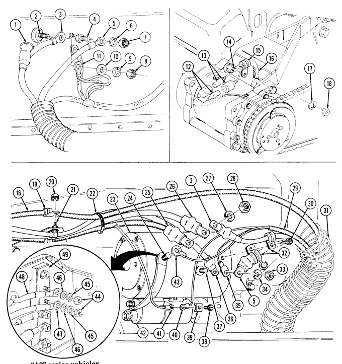
"A2" series vehicles
4-77. Starter Power Cables Replacement (Cont'D)
b. Installation 1. Install coil (16) on positive cable (11) and grommet cable (20). Route STE/ICE-R harness (14) and compressor harness (1) (M997 and M997A1 vehicles only) through coil (16), and place cables (11) and (20), STE/ICE-R harness (14), and compressor harness (1) (M997 and M997A1 vehicles only) in approximate mounting locations.
-
Install positive cable (11) and lead 6B/6C (37) on power stud (30) with washer (36), lockwasher (35), and nut (34). Tighten nut (34) 26 lb-ft (35 N•m). Slide rubber boot (29) over power stud (30).
-
Install ground cable (20) on ground stud (31) with lockwasher (32) and nut (33). Tighten nut (33) 75 lb-ft (102 N•m).
Perform step 4 for all vehicles except "A2" series vehicles. Perform steps 5 and 6 for M997A2, M1025A2, M1035A2, M1043A2, M1045A2, and M1097A2 vehicles only.
-
Install STE/ICE-R leads 81B (8) and 81A (9), positive accessory cable (10), and positive cable (11), (vehicles with winch or 200 amp alternator only) on positive post (7) with lockwasher (12) and nut (13). Tighten nut (13) 25-30 lb-ft (34-41 N•m).
-
Install lead 81B (8) on positive post (7) with lockwasher (12) and nut (13). Tighten nut (13) 25-30 lb-ft (34-41 N•m).
-
Install positive accessory cable (49) and positive cable (48) (vehicles with winch or 200 amp alternator only) on buss bar (44) with two washers (47), lockwashers (46), and nuts (45). Tighten nuts (45) 25-30 lb-ft (34-41 N•m).
-
Apply sealant to positive post (7) and cable terminals so that all exposed metallic surfaces are coated. The sealant should be evenly applied with a minimum thickness of .12 in. (3 mm).
-
Install lead 7C (22) (winch vehicles only), STE/ICE-R 3C lead (21), and ground cable (20) on negative post (23) with lockwasher (19) and nut (18). Tighten nut (18) 15-20 lb-ft (20-27 N•m).
-
Install leads 74A (27) and 74B (26) on solenoid (28) with clip (25) and screw (24).
-
Install two clamps (17) on positive cable (11) and ground cable (20) and secure to starter (6) with screws (15).
Perform steps 11 through 14 for M997, M997A1, and M997A2 vehicles only.
- Connect compressor harness leads (39) to compressor leads (38). 12. Install clamp (41) on compressor harness (1) and capscrew (40) with lockwasher (42) and nut (43). 13. Install clamp (2) on compressor harness (1) and cable bracket screw (4) with assembled locknut (3). 14. Install compressor harness (1) on alternator cable (10) and lead 81A (9) with tiedown strap (5).
4-77. Starter Power Cables Replacement (Cont'D)
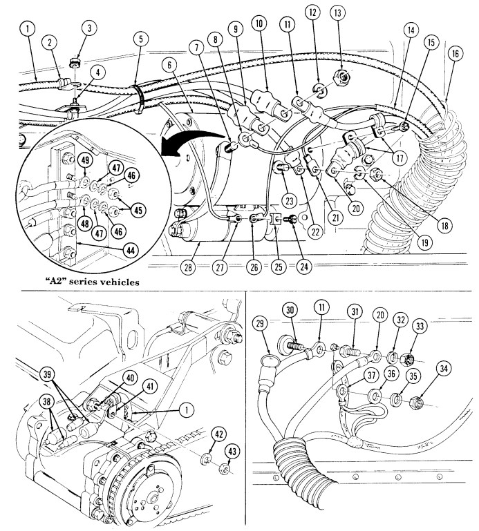
FOLLOW-ON TASKS: - Connect battery ground cable (para. 4-73) · Lower and secure hood (TM 9-2320-280-10).
4-78. Battery Holddown Replacement
This task covers: INITIAL SETUP: General mechanic's tool kit: TM 9-2320-280-10 disconnected (para. 4-73).
A. Removal B. Installation
Tools Equipment Condition
automotive (Appendix B, Item 1) Battery box cover removed (para. 10-35).
Battery ground cable disconnected (para. 4-73).
Manual References Battery interconnecting cable and positive cable
Tm 9-2320-280-24P General Safety Instructions
Wear safety goggles and rubber gloves, and do not smoke when performing battery maintenance.
Remove all jewelry.
Warnin G
Battery acid (electrolyte) is extremely harmful. Always wear safety goggles and rubber gloves, and do not smoke when performing battery maintenance. Severe injury will result if acid contacts eyes or skin.
Remove all jewelry such as rings, dog tags, bracelets, etc. If jewelry or disconnected battery ground cable contacts battery terminal, a direct short can result, causing instant heating of tools, severe injury to personnel, or damage to equipment.
A. Removal
-
Remove nut (8), screw (6), and interconnecting cable (4) from battery terminal clamp (5) and terminal post (7).
-
Remove four nuts (2) and holddown rods (1) from battery holddown (3), battery box (10) and brackets (9).
-
Remove battery holddown (3).
b. Installation 1. Install battery holddown (3) on batteries (11), battery box rods (1) and nuts (2).
(10), and brackets (9) with four holddown 2. Install interconnecting cable (4) on battery terminal clamp (5) at terminal post (7) with screw (6) and nut (8).
4-78. Battery Holddown Replacement (Cont'D)
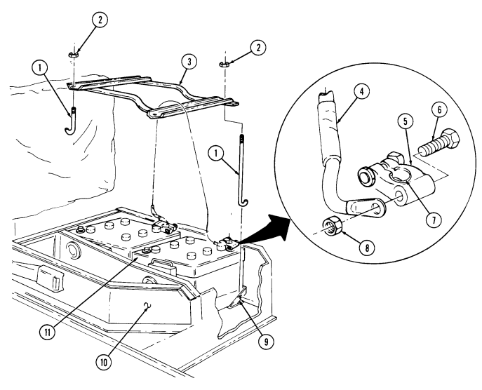
FOLLOW-ON TASKS: • Connect battery interconnecting cable and positive cable (para. 4-73)
- Connect battery ground cable (para. 4-73).
- Install battery box cover (para. 10-35).
4-79. Battery Replacement And Servicing
This task covers: a. Removal c. Installation b. Servicing INITIAL SETUP: Tools Equipment Condition General mechanic's tool kit: Battery holddown removed (para. 4-78).
automotive (Appendix B, Item 1) Manual References TM 9-6140-200-14 TM 9-2320-280-24P General Safety Instructions Wear safety goggles and rubber gloves, and do not smoke when performing battery maintenance.
Remove all jewelry.
Warnin G
Battery acid (electrolyte) is extremely harmful. Always wear safety goggles and rubber gloves, and do not smoke when performing battery maintenance. Severe injury will result if acid contacts eyes or skin. Remove all jewelry such as rings, dog tags, bracelets, etc. If jewelry or disconnected battery ground cable contacts battery terminal, a direct short can result, causing instant heating of tools, severe injury to personnel, or damage to equipment.
- Loosen four screws (4) and nuts (2) from four battery terminal clamps (3) and terminals (1). 2. Using battery clamp puller, remove four battery terminal clamps (3) from terminals (1). 3. Place cables (6) in a position to prevent arcing with batteries. 4. Remove batteries (5) from battery box (7).
b. Servicing
For battery testing and servicing instructions refer to TM 9-6140-200-14.
C. Installation
-
Position batteries (5) in box (7).
-
Ensure negative (1) terminal posts are correctly located. Cables must reach their respective terminals without stretching.
-
Install four battery terminal clamps (3) to battery terminals (1).
-
Tighten four nuts (2) and screws (4) on battery terminal clamps (3) and battery terminals (1).
4-79. Battery Replacement And Servicing (Cont'D)
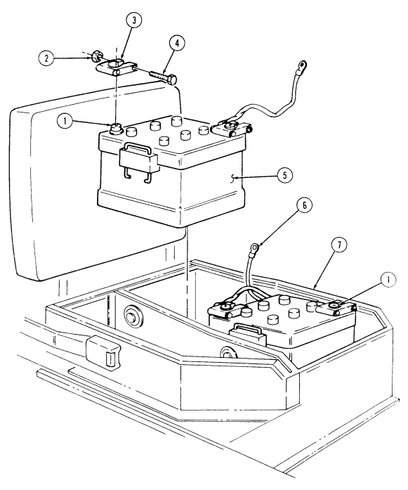
FOLLOW-ON TASK: Install battery holddown (para. 4-78).
4-80. Battery Tray Maintenance
This task covers:
a. Removal c. Preventive Modification b. Cleaning and Inspection d. Installation
INITIAL SETUP: Tools General mechanic's tool kit: automotive (Appendix B, Item 1)
Materials/Parts
Four locknuts (Appendix G, Item 70) Sodium bicarbonate (Appendix C, Item 49) a. Removal Manual References TM 9-6140-200-14 TM 9-2320-280-24P Equipment Condition Battery holddown removed (para. 4-78).
Remove four locknuts (6), washers (2), capscrews (1), washers (2), and battery tray (3) from battery box (5). Discard locknuts (6).
b. Cleaning and Inspection
For additional information on battery box tray cleaning, refer to TM 9-6140-200-14.
- Clean battery tray (3) with baking soda solution. 2. Inspect battery tray (3) for damage. Replace if damaged. 3. Inspect battery cable protectors (4) and battery compartment seals (7) for damage. Replace if damaged.
c. Preventive Modification
-
The following step will prevent water from accumulating in the battery tray.
-
Refer to hole diagram for location of holes.
Locate, mark, and drill four 1/2 inch holes in battery tray (3).
d. Installation Install battery tray (3) on battery box (5) with four washers (2), capscrews (1), washers (2), and locknuts (6). Tighten locknuts (6) to 6 lb-ft (8 N•m).
4-80. Battery Tray Maintenance (Cont'D)
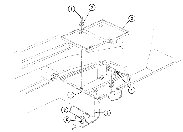
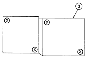
HOLE DIAGRAM
FOLLOW-ON TASK: Install battery holddown (para. 4-78).
4-81. Slave Receptacle And Cable Maintenance
This task covers: a. Removal c. Installation b. Inspection INITIAL SETUP:
Tools
General mechanic's tool kit: automotive (Appendix B, Item 1)
Materials/Parts
Lockwasher (Appendix G, Item 148) Lockwasher (Appendix G, Item 141) Two lockwashers (Appendix G, Item 133) (serial numbers 1 through 99,999) Two lockwashers (Appendix G, Item 155) (serial numbers 100,000 and above) Four plain-assembled nuts (Appendix G, Item 200) (old configuration) Four plain-assembled nuts (Appendix G, Item 199) (new configuration) Grease (Appendix C, Item 24)
| anual Reeferences |
|---|
| TM 9-2320-280-24P |
Equipment Condition
- Battery tray removed (para. 4-80). - TOW wiring harness removed from power feed stud and shunt (para. 11-67). M966, M966A1 M1036, M1045, M1045A1, M1045A2, M1046, M1046A1, M1121 only.
A. Removal
-
Remove capscrew (8), lockwasher (9), slave negative cable (10), and battery negative cable (11) from shunt (1). Discard lockwasher (9).
-
Remove nut (7), lockwasher (6), washer (5), battery positive cable (4), and slave positive cable (3) from power feed stud (2). Discard lockwasher (6).
-
Remove four plain-assembled nuts (13), capscrews (18), receptacle (19), and cover (17) from battery box (12). Discard plain-assembled nuts (13).
-
Prior to removal, tag leads for installation. - Perform steps 4 through 7 for vehicles with serial numbers 1 through 99,999.
-
Perform steps 8 through 10 for vehicles with serial numbers 100,000 and above.
-
Slide rubber boot (14) back to allow access to slave receptacle (19) connections. 5. Remove capscrew (21), lockwasher (20), slave negative cable (10) from receptacle (19). Discard lockwasher (20).
-
Remove capscrew (16), lockwasher (15), slave positive cable (3) from receptacle (19). Discard lockwasher (15).
-
Remove rubber boot (14). 8. Loosen compression nut (23) on backshell (22) and remove backshell (22) from receptacle (19). 9. Remove capscrew (21), lockwasher (20), and slave negative cable (10) from receptacle (19). Discard lockwasher (20).
-
Remove capscrew (16), lockwasher (15), and slave positive cable (3) from receptacle (19). Discard lockwasher (15).
4-81. Slave Receptacle And Cable Maintenance (Cont'D)
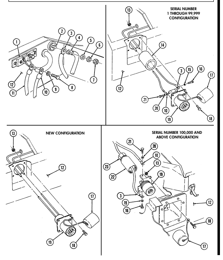
4-81. Slave Receptacle And Cable Maintenance (Cont'D)
b. Inspection 1. Inspect cover (17) for breaks or cracks. Replace if damaged. 2. Inspect cables (3) and (10) for damage. Repair if damaged (reefer to para. 4-73). 3. Inspect rubber boot (14) for tears. Replace if torn. c. Installation
When making electrical connections, ensure hookup of positive (+) cable to positive electrode and negative (–) cable to negative electrode of the receptacle.
-
Perform steps 1 through 4 for vehicles with serial numbers 1 through 99,999.
-
Perform steps 5 through 9 for vehicles with serial numbers 100,000 and above.
-
Tighten compression nut (23) on backshell (22).
-
Install rubber boot (14) by sliding slave negative cable (10) and slave positive cable (3) through rubber boot (14).
-
Install receptacle (19) by attaching slave positive cable (3) to receptacle (19) with lockwasher (15) and capscrew (16).
-
Attach slave negative cable (10) to receptacle (19) with lockwasher (20) and capscrew (21). 4. Slide rubber boot (14) forward to cover slave receptacle (19) connection. 5. Attach slave positive cable (3) to receptacle (19) with lockwasher (15) and capscrew (16). 6. Attach slave negative cable (10) to receptacle (19) with lockwasher (20) and capscrew (21). 7. Using grease, coat receptacle (19) terminals, all exposed metal on rear of receptacle (19), and area under cover (17) on front of receptacle (19).
-
Install backshell (22) on receptacle (19).
-
Attach receptacle (19) to battery box (12) by installing cover (17) to receptacle (19) with four capscrews (18) and plain-assembled nuts (13).
-
Attach slave positive cable (3) and battery positive cable (4) to power feed stud (2) with washer (5), lockwasher (6), and nut (7). Tighten nut (7) 26 lb-ft (35 N•m).
-
Attach battery negative cable (11) and slave negative cable (10) to shunt (1) with lockwasher (9) and capscrew (8). Tighten capscrew (8) 96 lb-in. (11 N•m).
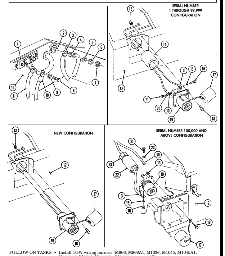
4-81. Slave Receptacle And Cable Maintenance (Cont'D)
M1045A2, M1046, M1046A1, M1121) (para. 11-67).
- Install battery tray (para. 4-80).
4-82. Winch Power Cable Replacement
This task covers: INITIAL SETUP: Applicable Models M1026, M1026A1, M1036, M1038, M1038A1, M1042, M1044, M1044A1, M1046, M1046A1 Tools General mechanic's tool kit: automotive (Appendix B, Item 1)
Materials/Parts
Lockwasher (Appendix G, Item 135) Three tiedown straps (Appendix G, Item 307) Assembled locknut (Appendix G, Item 131)
a. Removal b. Installation
| Manual References |
|---|
| TM 9-2320-280-24P |
Equipment Condition Battery ground cable disconnected (para. 4-73).
A. Removal
-
Remove three tiedown straps (2) from ventline (8), lead 7 (4), and lead 6 (6). Discard tiedown straps (2).
-
Remove capscrew (5) from lead 7 (4) and winch (9). 3. Remove nut (7) from lead 6 (6) and solenoid (3). 4. Remove two screws (1) and clamps (10) from lead 7 (4), lead 6 (6), and winch (9). 5. Remove screw (14), lockwasher (12), nut (11), and clamp (13) from lead 7 (4), lead 6 (6), and bracket (15). Discard lockwasher (12).
-
Remove two screws (16) and clamps (17) from lead 7 (4), lead 6 (6), and airlift bracket (18). 7. Remove assembled locknut (19), capscrew (21), and clamp (22) from lead 7 (4), lead 6 (6) and bracket (20). Discard assembled locknut (19).
-
Remove nut (25) and lead 7 (4) from starter negative stud (26). 9. Remove nut (23) and lead 6 (6) from starter positive stud (24).
B. Installation
-
Install lead 6 (6) on starter positive stud (24) with nut (23). Tighten nut (23) to 25-30 lb-ft (34-41 N•m). 2. Install lead 7 (4) on starter negative stud (25) with nut (26). Tighten nut (26) to 15-20 lb-ft (20-27 N•m). 3. Install lead 7 (4) and lead 6 (6) on bracket (20) with capscrew (21), assembled locknut (19), and clamp (22).
-
Install lead 7 (4) and lead 6 (6) on airlift bracket (18) with two screws (16) and clamps (17). 5. Install lead 7 (4) and lead 6 (6) on bracket (15) with screw (14), lockwasher (12), nut (11), and clamp (13).
-
Install lead 7 (4) and lead 6 (6) on winch (9) with two clamps (10) and screws (1). 7. Install lead 6 (6) on solenoid (3) with nut (7). 8. Install lead 7 (4) on winch (6) with capscrew (5). 9. Install lead 6 (6) and lead 7 (4) on vent line (8) with three tiedown straps (2).
4-82. Winch Power Cable Replacement (Cont'D)
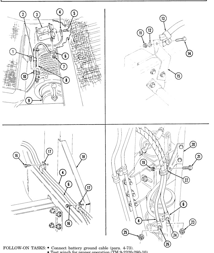
4-83. Shunt Replacement
This task covers: INITIAL SETUP:
Tools
General mechanic's tool kit: automotive (Appendix B, Item 1) Materials/Parts Two lockwashers (Appendix G, Item 171) Two assembled locknuts (Appendix G, Item 130) Two lockwashers (Appendix G, Item 178) Lockwasher (Appendix G, Item 148) Personnel Required One mechanic One assistant
A. Removal B. Installation
Manual References TM 9-2320-280-24P Equipment Condition Batteries removed (para. 4-79).
Prior to removal, tag leads for installation.
A. Removal
-
Remove two screws (10) and lockwashers (8) and disconnect leads 9A (15), 8A (6), 7B and 7D (14) from shunt (16). Discard lockwashers.
-
Remove nut (1) and lockwasher (2) securing starter cable (3) to capscrew (9) and disconnect starter cable (3). Discard lockwasher (2).
-
Remove nut (18), lockwasher (17), and capscrew (9) from shunt (16). Discard lockwasher (17). 4. Remove capscrew (11), lockwasher (12), and negative cables (13) from shunt (16). Discard lockwasher (12).
-
Remove two assembled locknuts (7), washers (5), capscrews (4), washers (5), and shunt (16) from battery box (19). Discard assembled locknuts (7).
B. Installation
-
Install shunt (16) to battery box (19) with two washers (5), capscrews (4), washers (5), and assembled locknuts (7). Tighten assembled locknuts (7) to 8 lb-ft (11 N.m).
-
Install negative cables (13) to shunt (16) with lockwasher (12) and capscrew (11). Tighten capscrew (11) to 8 lb-ft (11 N•m).
-
Install capscrew (9) to shunt (16) with lockwasher (17) and nut (18). Tighten nut (18) to 75 lb-ft (102 N•m).
-
Connect starter cable (3) to capscrew (9) with lockwasher (2) and nut (1). Tighten nut (1) to 18 to 22 lb-ft (24-30 N•m).
-
Instal leads 9A (15), 8A (6), 7B, and 7D (14) on shunt (16) with two lockwashers (8) and screws (10).
4-83. Shunt Replacement (Cont'D)
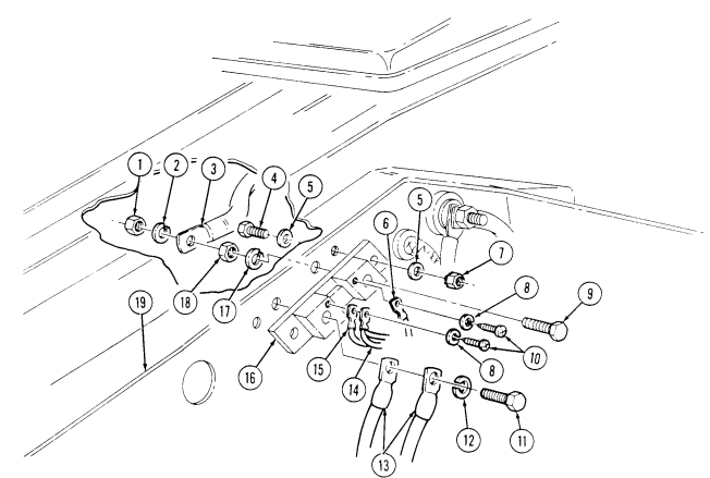
4-84. Hood Wiring Harness Replacement
This task covers: a. Removal c. Installation
Initial Setup:
Tools General mechanic's tool kit: automotive (Appendix B, Item 1) Materials/Parts Two locknuts (Appendix G, Item 74) (A2 Series and M1123) Two locknuts (Appendix G, Item 102) (Basic and A1 Series) Antiseize compound (Appendix C, Item 13) Manual References TM 9-2320-280-10 TM 9-2320-280-24P Equipment Condition
-
Blackout drive light assembly removed (para. 4-50).
-
Side marker light lenses and lamp removed (para. 4-54).
Prior to removal, tag leads for installation.
A. Removal
-
Disconnect connector plug (2) from connector receptacle (1). 2. Remove four capscrews (7) and washers (6) from left cover plate (5) and hood (3). 3. Remove two clips (4) from cover plate (5) and remove cover plate (5). 4. Disconnect harness leads 489C (16) from left side marker light terminal (15). 5. Disconnect harness leads 20E (9), 461B (20), and 491C (19) from three left composite light terminals (8). 6. Remove locknut (12), screw (11), and left side marker light ground 92C (10) from hood (3). Discard locknut (12).
-
Remove capscrew (14), washer (13), and left composite light ground 92B (17) from bus bar (18).
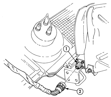
4-84. Hood Wiring Harness Replacement (Cont'D)
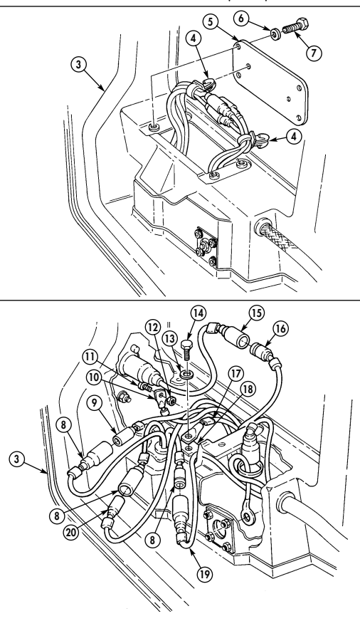
4-84. Hood Wiring Harness Replacement (Cont'D)
-
Remove three capscrews (1) and washers (2) from right cover plate (3) and hood (5). 9. Remove two clips (4) from cover plate (3) and remove cover plate (3).
-
Disconnect harness lead 489D (6) at right side marker light terminal (7). 11. Disconnect harness leads 20F (14), 460B (15), and 491D (16) at right composite light terminals (13). 12. Remove locknut (10), screw (12), and right side marker light ground 92D (11) from hood (5).
Discard locknut (10).
- Remove capscrew (9), washer (8), and right composite light ground 92A (18) from bus bar (17). 14. Disconnect harness leads 17E (22), 18C (23), and 91D (25) at left headlight connectors (26). 15. Disconnect harness leads 17F (22), 18D (23), and 91C (25) at right headlight connectors (26). 16. Remove three capscrews (27), clamps (28), washers (29), and harness (21) from hood (5). 17. Remove two screw and washer assemblies (19), clamps (20), and harness (21) from hood (5).
Use care when removing harness. Failure to do so will cause damage to harness.
- Remove grommet (24) and harness (21) from hood (5).

4-84. Hood Wiring Harness Replacement (Cont'D)
b. Installation 1.
Position harness (21) on hood (5) in approximate mounting position.
Use care when routing harness. Failure to do so will cause damage to harness.
Insert harness (21) and grommets (24) through opening in hood (5).
Connect harness leads 17E (22), 18C (23), and 91D (25) at left headlight connetors (26).
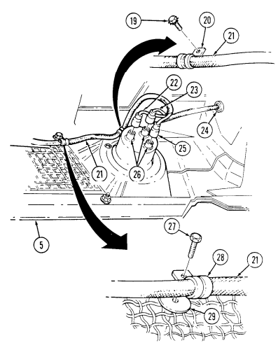
Connect harness leads 17F (22), 18D (23), and 91C (25) at right headlight connectors (26). Secure harness (21) to hood (5) with three washers (29), clamps (28), and screws (27). Finger tighten screws (27). Secure harness (21) to hood (5) with two screw and washer assemblies (19) and clamps (20). Finger tighten screw and washer assemblies (19).
4-84. Hood Wiring Harness Replacement (Cont'D)
-
Apply antiseize compound to left composite light ground 92B (10) and install on bus bar (11) with washer (6) and capscrew (7).
-
Apply antiseize compound to left side marker light ground 92C (3) and install on hood (16) with locknut (5) and screw (4).
-
Connect harness leads 20E (2), 461B (15), and 491B (14) at left composite light terminals (1).
-
Connect harness lead 489C (9) at left side marker light terminal (8). 11. Insert harness lead 19B (12) and harness lead 92E (13) through opening in hood (16). 12. Install leads (12) and (13) with two clips (17) on left cover plate (18). 13. Install left cover plate (18) with four washers (19) and capscrews (20).
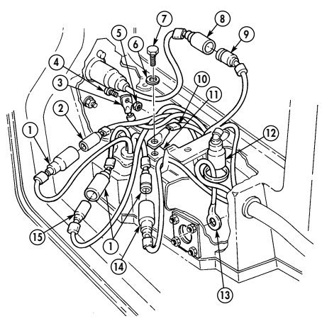
4-84. HOOD WIRING HARNESS REPLACEMENT (Cont'd)
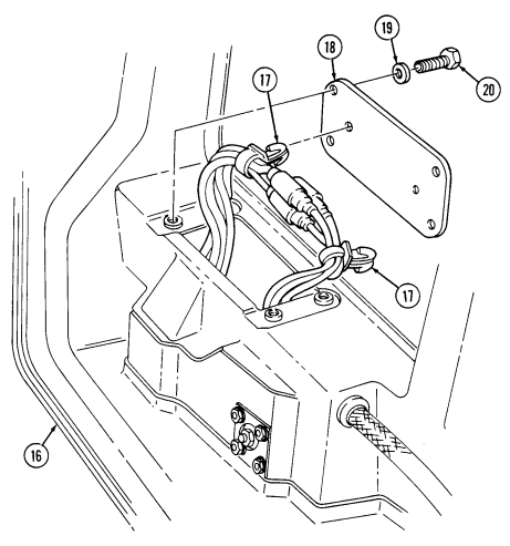
4-84. Hood Wiring Harness Replacement (Cont'D)
-
Apply antiseize compound to right composite light ground 92A (13) and install on bus bar (12) with washer (3) and capscrew (4).
-
Apply antiseize compound to right side marker light ground 92C (6) and install on hood (14) with screw (7) and locknut (5).
-
Connect harness leads 20F (9), 460B (10), and 491D (11) at right composite light terminals (8). 17. Connect harness lead 489D (1) at right side marker light terminal (2). 18. Secure leads with two clips (18) and install clips (18) on right cover plate (17). 19. Install right cover plate (17) to hood (14) with three washers (16) and capscrews (15). 20. Connect connector plug (20) to connector receptacle (19). 21. Tighten all clamps securing harness.
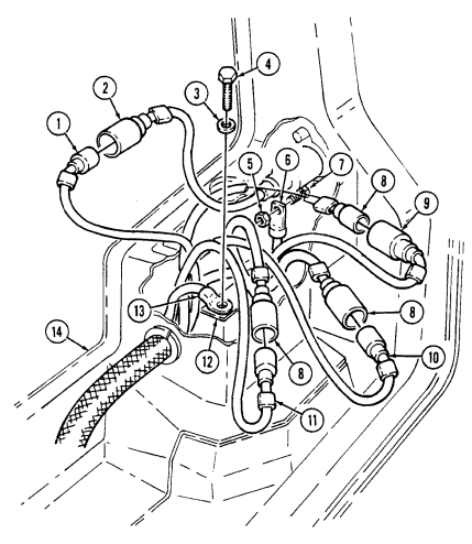
4-84. Hood Wiring Harness Replacement (Cont'D)
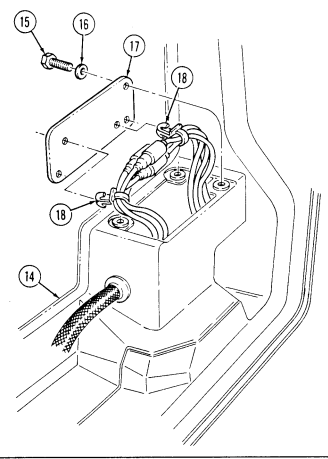
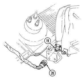
FOLLOW-ON TASKS: - Install side marker light lenses and lamp (para. 4-54).
- • Install drive blackout light (para. 4-50).
· Check front lights for proper operation (TM 9-2320-280-10).
4-85. Wiring Harness Connector Repair
This task covers: a. Terminal-Type Cable Connector Repair e. Receptacle Assembly Repair c. Female Cable Connector Repair Assembly Repair d. Connector Assembly Repair b. Male Cable Connector Repair f. Protective Control Box Lower Cannon Plug INITIAL SETUP: General mechanic's tool kit: Battery ground cable disconnected (para. 4-73).
automotive (Appendix B, Item 1) Connector repair kit (Appendix B, Item 165) General Safety Instructions Manual References TB SIG-222 TM 9-2320-280-24P Tools Equipment Condition Remove all jewelry.
Warnin G
Remove all jewelry such as rings dog tags, bracelets, etc. If jewelry or disconnected battery ground cable contacts battery terminal, a direct short can result, causing instant heating of tools, severe injury to personnel, or damage to equipment.
A. Terminal-Type Connector Repair
-
Strip cable insulation (1) from cable (2) to equal depth of terminal well (4).
-
Slide insulator (3) over cable insulation (1).
 3. Insert cable (2) into terminal well (4) and crimp. 4. Slide insulator (3) over crimped end of terminal (5).
B. Male Cable Connector Repair
-
Strip cable insulation (6) from cable (7) to equal depth of terminal well (10).
-
Slide shell (8) over cable insulation (6). 3. Insert cable (7) into terminal well (10) and crimp.
 4. Place slotted washer (9) over crimped junction at terminal (11).
- Slide shell (8) over slotted washer (9) and terminal (11).
4-85. Wiring Harness Connector Repair (Cont'D)
c. Female Cable Connector Repair 1. Strip cable insulation (12) from cable (13) to equal depth of terminal well (16).
-
Slide shell (14) and sleeve (15) over cable insulation (12). 3. Insert cable (13) into terminal well (16) and crimp.
-
Slide shell (14) and sleeve (15) over terminal (17).

d. Connector Assembly Repair
Refer to TB SIG-222 for soldering instructions.
-
Strip cable insulation (18) to depth of solder wells (21) on inserts (22).
-
Slide cable ends (25) through grommet retaining nut (19) and grommet (20).
-
Place cable ends (25) into solder wells (21) and solder.
-
Slide grommet (20) over inserts (22) and press into shell assembly (23) and coupling nut (24) until seated.
-
Screw grommet retaining nut (19) into shell assembly (23) until seated.
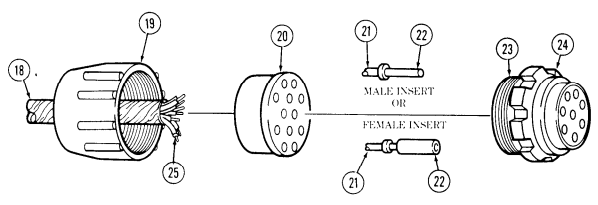
4-85. Wiring Harness Connector Repair (Cont'D)
e. Receptacle Assembly Repair
Refer to TB SIG-222 for soldering instructions.
Strip cable insulation (1) to depth of solder wells (5) on inserts (6).
Slide cable ends (3) through grommet retaining nut (2) and grommet (4).
Place cable ends (3) into solder wells (5) and solder. Slide grommet (4) over inserts (5) and press into receptacle (7) until seated.

Screw grommet retaining nut (2) into receptacle (7) until seated.
F. Protective Control Box Lower Cannon Plug Assembly Repair
-
Strip cable insulation (8) to depth of solder wells (16) on inserts (14).
-
Slide cable ends (10) through grommet retaining nut (9) and grommet 3. Slide insulation sleeving (17) over lead 67A (18).
(11).
- Place cable ends (10) into solder wells (16) and solder.
Ensure insulation sleeving passes through grommet to provide a water tight fit.
Slide insulation sleeving (17) up to solder well end (15), and heat shrink insulation sleeving (17). Slide grommet (11) over inserts (14) and press into shell assembly (12) and coupling nut (13) until seated.
Screw grommet retaining nut (9) into shell assembly (12) until seated.

FOLLOW-ON TASK: Connect battery ground cable (para. 4-73).
Section Vii. Ambulance Electrical System Maintenance 4-86. Electrical System Maintenance Task Summary
| Applicable Models | Materials/Parts | M997A2, M1025A2, M1035A2, | Five lockwashers (Appendix G, Item 150) |
|---|---|---|---|
| M1043A2, M1045A2, M1097A2 | Lockwasher (Appendix G, Item 141) | Silicone compound (Appendix C, Item 48) | |
| Tools | General mechanic's tool kit: | Equipment Condition | |
| automotive (Appendix B, Item 1) | Battery removed (para. 4-79). | ||
| a. Removal | |||
| 1. | Remove five nuts (9), lockwashers (8), and washers (7), engine harness cable (6), alternator | cable (10), battery cable (11), umbilical power cable (12) (M1097A2 vehicles only), and slave | |
| receptacle cable (13) from buss bar (2). Discard lockwashers (8). | 2. | Remove nut (5), lockwasher (4), washer (3), and buss bar (2) from power feed through stud (1). | |
| Discard lockwasher (4). | |||
| b. Installation | |||
| 1. | Install buss bar (2) to power feed through stud (1) with washer (3), lockwasher (4), and nut (5). | 2. | Install engine harness cable (6), alternator cable (10), battery cable (11), umbilical power cable (12) |
| (M1097A2 vehicles only), and slave receptacle cable (13) on buss bar (2) with five washers (7), | lockwashers (8), and nuts (9). | ||
| 3. | Apply silicone compound to buss bar (2), so that all exposed metallic surfaces are coated. | ||
| FOLLOW-ON TASK: Install battery (para. 4-79). |
4-86. Electrical System Maintenance Task Summary (Cont'D)
| This task covers: | ||
|---|---|---|
| a. Removal | c. Preventive Modification | |
| b. Cleaning and Inspection | d. Installation | |
| INITIAL SETUP: | ||
| Tools | Manual References | |
| General mechanic's tool kit: | TM 9-6140-200-14 | |
| automotive (Appendix B, Item 1) | TM 9-2320-280-24P | |
| Materials/Parts | Equipment Condition | |
| Four locknuts (Appendix G, Item 70) | Battery holddown removed (para. 4-78). | |
| Sodium bicarbonate (Appendix C, Item 49) | ||
| a. Removal | ||
| Remove four locknuts (6), washers (2), capscrews (1), washers (2), and battery tray (3) from battery box | ||
| (5). Discard locknuts (6). | ||
| b. Cleaning and Inspection | ||
| NOTE |
| 2. Inspect battery tray (3) for damage. Replace if damaged. |
|---|
| 3. Inspect battery cable protectors (4) and battery compartment seals (7) for damage. Replace if |
| damaged. |
| c. Preventive Modification |
| NOTE |
| - The following step will prevent water from accumulating in the |
| battery tray. |
| - Refer to hole diagram for location of holes. |
| Locate, mark, and drill four 1/2 inch holes in battery tray (3). |
4-87. Ceiling Light Assembly Maintenance
Dome and blackout light assemblies are removed and installed basically the same. This procedure covers the dome light assembly.
4-87. Ceiling Light Assembly Maintenance (Cont'D)
- Remove two screws (5) and lens (6) from light assembly (4).
For removal and installation of rivets, refer to para. 10-66.
-
Remove four rivets (7) from light assembly (4) and duct (1). Pull light assembly (4) away from duct (1) to allow access to leads.
-
Disconnect two leads (3) from harness connectors (2). Remove light assembly (4).
-
Connect two leads (3) to harness connectors (2).
-
Install light assembly (4) to duct (1) with four rivets (7).
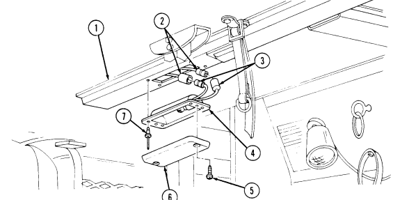 3. Install lens (6) to light assembly (4) with two screws (5).
FOLLOW-ON TASK: Check operation of ceiling light (TM 9-2320-280-10).
4-88. Spotlight Assembly Maintenance
This task covers:
a. Removal b. Installation
| Tools | Manual Reeferences |
|---|---|
| General mechanic's tool kit: | TM 9-2320-280-24P |
| automotive (Appendix B, Item 1) | Equipment Condition |
| Materials/Parts | - Battery tray removed (para. 4-80). |
| INITIAL SETUP: |
|---|
M996, M996A1, M997, M997A1, and M997A2 spotlight replacements are basically the same. This procedure covers the M996 and M996A1.
A. Removal
- Remove four screws (8) and duct (7) from ceiling (1) and pull duct (7) away for access to clamp (5). 2. Remove screw (6), nut (4), and clamp (5) from duct (7). Remove duct (7). 3. Disconnect spotlight leads (3) from harness leads (2). Remove light assembly (9) from quick disconnect base (10).
b. Installation 1. Install light assembly (9) on quick disconnect base (10) and connect spotlight leads (3) to harness leads (2).
- Install clamp (5) on light assembly (9) and duct (7) with screw (6) and nut (4). 3. Install duct (7) on ceiling (1) with four screws (8).
4-88. Spotlight Assembly Maintenance (Cont'D)
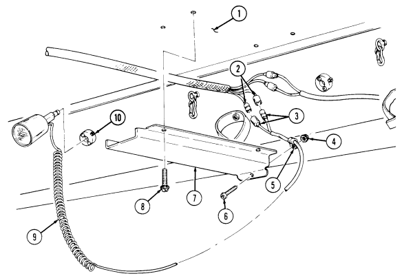
FOLLOW-ON TASKS: - Connect battery ground cable (para. 4-73).
· Check operation of spotlight (TM 9-2320-280-10)
4-89. Spotlight Socket Maintenance
This task covers: a. Removal c. Adjustment b. Installation INITIAL SETUP: Applicable Models Manual References M996, M996A1, M997, M997A1, M997A2 TM 9-2320-280-24P Tools General mechanic's tool kit: automotive (Appendix B, Item 1)
-
Pull spotlight (5) from socket (2).
-
Remove two screws (1) and socket (2)from body (4).
b. Installation 1. Install socket (2) on body (4) with two screws (1).
- Install spotlight (5) into socket (2).
c. Adjustment Adjust detent screw (3) for proper positioning of spotlight (5).
4-89. Spotlight Socket Maintenance (Cont'D)
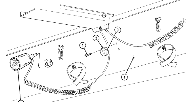
5
4-90. Electrical Outlet/Bracket Maintenance
This task covers: INITIAL SETUP: Applicable Models Equipment Condition General mechanic's tool kit: automotive (Appendix B, Item 1) Manual References TM 9-2320-280-10 TM 9-2320-280-24P
A. Removal B. Installation
M996, M996A1, M997, M997A1, M997A2 Battery ground cable disconnected (para. 4-73).
Tools Rear doors opened (TM 9-2320-280-10).
Note
Prior to removal, tag leads for installation.
A. Removal
- Slide rubber boot (1) away from outlet (4). 2. Remove two screws (3) and pull outlet (4) away from bracket (2). 3. Loosen screw (8) and move shield (9) away from screws (7).
(10) and remove outlet (4).
- Remove two screws (7), disconnect harness leads 714B (11) and 790A
Note
Perform step 5 only if removing bracket.
- Remove three screws (6) and bracket (2) from body (5).
B. Installation
-
Install bracket (2) on body (5) with three screws (6).
-
Connect leads 714B (11) and 790A (10) to outlet (4) with two screws (7).
-
Position shield (9) over screws (7) and tighten screw (8). 4. Install outlet (4) on bracket (2) with two screws (3). 5. Slide boot (1) over back of outlet (4).
4-90. ELECTRICAL OUTLET/BRACKET MAINTENANCE (Cont'd)
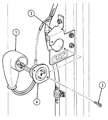
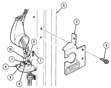
4-91. Rear Steps Blackout Switch Bracket Replacement
This task covers: INITIAL SETUP: Applicable Models M996, M996A1, M997, M997A1, M997A2 Tools General mechanic's tool kit: automotive (Appendix B, Item 1)
a. Removal b. Installation
Manual References TM 9-2320-280-24P Equipment Condition Blackout switch removed (para. 4-93).
Materials/Parts Two blind rivets (Appendix G, Item 242)
For instructions on replacement of rivets, refer to para. 10-66.
a. Removal Remove two rivets (1) and switch bracket (2) from body (3).
b. Installation Install bracket (2) on body (3) with two rivets (1).
4-91. Rear Steps Blackout Switch Bracket Replacement (Cont'D)
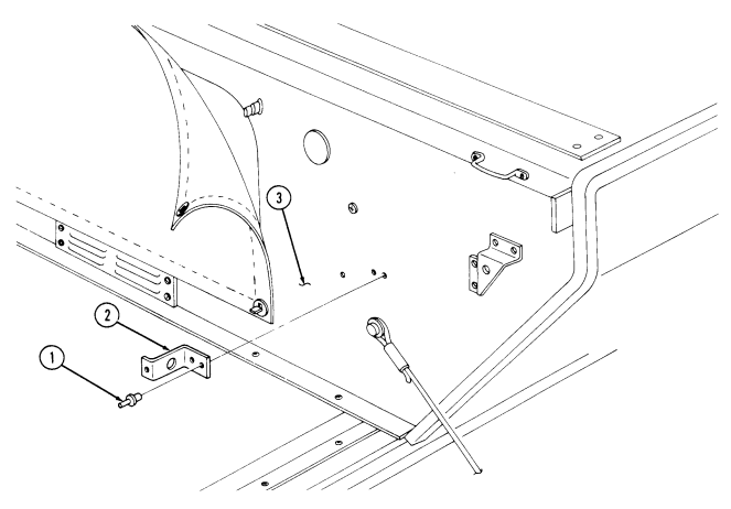
FOLLOW-ON TASK: Install blackout switch (para. 4-93).
4-92. Rear Steps Blackout Switch Replacement
This task covers: INITIAL SETUP: Applicable Models M996, M996A1, M997, M997A1, M997A2 Tools General mechanic's tool kit: automotive (Appendix B, Item 1)
a. Removal b. Installation
Manual References TM 9-2320-280-10 TM 9-2320-280-24P Equipment Condition
- Rear steps lowered (TM 9-2320-280-10). - Battery ground cable disconnected (para. 4-73).
Materials/Parts Lockwasher (Appendix G, Item 168)
Prior to removal, tag leads for installation.
A. Removal
-
Remove three screws (1) and cover (2) from body (3) and bracket (5). 2. Remove grommet (4) from body (3). 3. Remove nut (11), lockwasher (10), and light switch (6) from bracket (5) and remove adjusting nut (12). Discard lockwasher (10).
-
Pull light switch leads (7) through hole in body (3). 5. Disconnect light switch leads (7) from harness leads 791C (8) and 791D (9). Remove light switch (6).
B. Installation
-
Connect light switch leads (7) to harness leads 791C (8) and 791D (9). Push through body (3). 2. Install grommet (4) in body (3). 3. Position adjusting nut (12) on switch (6) about halfway out on threads. Install switch (6) to bracket (5) with lockwasher (10) and nut (11).
-
Slowly raise rear steps to latched position while listening for switch (6) to "click". If necessary, adjust switch (6) in or out to ensure switch (6) clicks (closed) when steps are in raised and latched position.
-
Install cover (2) to body (3) and bracket (5) with three screws (1).
4-92. REAR STEPS BLACKOUT SWITCH REPLACEMENT (Cont'd)
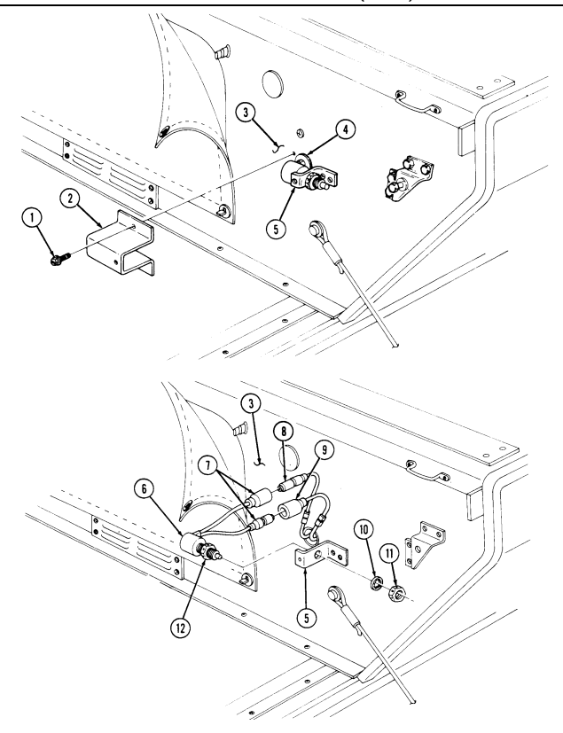
FOLLOW-ON TASK: Connect battery ground cable (para. 4-73).
4-93. Rear Door Blackout Switch/Bracket Maintenance
This task covers: INITIAL SETUP: Applicable Models M996, M996A1, M997, M997A1, M997A2 Tools General mechanic's tool kit: automotive (Appendix B, Item 1) Materials/Parts Assembled locknut (Appendix G, Item 131) Two lockwashers (Appendix G, Item 169) Two locknuts (Appendix G, Item 76)
A. Removal B. Installation
Manual References TM 9-2320-280-10 TM 9-2320-280-24P Equipment Condition
-
Battery ground cable disconnected (para. 4-73).
-
Rear doors lowered (TM 9-2320-280-10).
a. Removal 1.Remove two locknuts (6), washers (2), capscrews (3), and washers (2) from bracket (1) and bracket (7).
Discard locknuts (6).
Prior to removal, tag leads for installation.
2.Disconnect two leads (4) from leads (5). Remove bracket (1). 3.Remove two screws (18), lockwashers (17), and leads (14) and (16) from switch (15). Discard lockwashers (17).
4.Remove two nuts (13), washers (12), screws (9), switch (15), switch lever (11), and spacer plate (10) from bracket (1).
Perform step 5 only if wiring harness is damaged.
5.Remove assembled locknut (20) screw (8), clamp (19) and wiring harness (21) from bracket (1).
Discard assembled locknut (20).
b. Installation
Perform step 1, only if wiring harness was removed.
1.Install clamp (19) and wiring harness (21) on bracket (1) with screw (8) and assembled locknut (20).
2.Install spacer plate (10), switch lever (11), and switch (15) on bracket (1) with two screws (9), washers (12), and nuts (13).
3.Install leads (14) and (16) on switch (15) with two lockwashers (17) and screws (18). 4.Connect two leads (4) to leads (5). 5.Install bracket (1) on brackets (7) with two washers (2), capscrews (3), washers (2), and locknuts (6).
4-93. REAR DOOR BLACKOUT SWITCH/BRACKET MAINTENANCE (Cont'd)
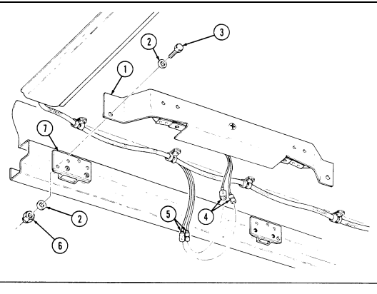
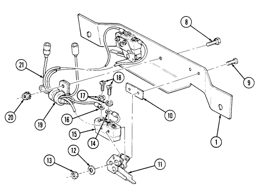
FOLLOW-ON TASKS: - Connect battery ground cable (para. 4-73).
- Check operation of interior blackout lights (TM 9-2320-280-10).
4-94. Bulkhead Door Blackout Switch And Bracket Maintenance
This task covers:
| INITIAL SETUP: |
|---|
| 4-119. | Control Box Electrical Plug and Receptacle | 4-280 |
|---|---|---|
| Replacement | ||
| 4-120. | Control Box Relay Replacement | 4-282 |
| 4-121. | Condenser Fan/Pressure Switch Wiring | 4-284 |
| Harness Replacement (M997, M997A1, M997A2) |
a. Removal b. Installation
Materials/Parts Four lockwashers (Appendix G, Item 169)
A. Removal
- Remove two screws (5) and washers (6) from switch cover (7) and bracket (4). Slide cover (7) away from switch (14) to allow access to switch (14).
Prior to removal, tag leads for installation.
-
Remove two screws (10) lockwashers (11), and two leads (12) and (13) from switch (14). Discard lockwashers (11).
-
Remove cover (7) and grommet (9) from wiring harness (8). 4. Remove two nuts (1), lockwashers (2), screws (16), switch (14), and switch lever (15) from bracket (4).
Discard lockwashers (2).
- Remove two screws (3) and bracket (4) from body (17).
B. Installation
- Install bracket (4) on body (17) with two screws (3). 2. Install switch (14) and switch lever (15) on bracket (4) with two screws (16), lockwashers (2), and nuts (1). 3. Install cover (7) and grommet (9) on wiring harness (8). 4. Connect two leads (12) and (13) to switch (14) with two lockwashers (11) and screws (10). 5. Slide cover (7) over switch (14) on bracket (4) with two washers (6) and screws (5).
4-94. Bulkhead Door Blackout Switch And Bracket Maintenance (Cont'D)
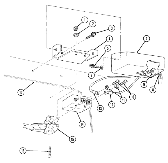
FOLLOW-ON TASKS: - · Connect battery ground cable (para. 4-73).
· Check operation of interior blackout light (TM 9-2320-280-10).
STORE LES
4-95. Backup Light Assembly Maintenance (M996, M996A1, M997, M997A1, M997A2)
This task covers:
| Applicable Models |
|---|
INITIAL SETUP: M996, M996A1, M997, M997A1, M997A2 Tools General mechanic's tool kit: automotive (Appendix B, Item 1)
Materials/Parts
Four lockwashers (Appendix G, Item 136) Two lockwashers (Appendix G, Item 139)
A. Light Assembly Removal B. Light Assembly Installation A. Light Assembly Removal
| Manual References ________________ |
|---|
| TM 9-2320-280-10 |
| TM 9-2320-280-24P |
| Equipment Condition __________________ |
| Battery ground cable disconnected (para. 4-73). |
-
Remove four screws (3) and lockwashers (2) from plate (6) and body (1). Pull plate (6) away from body (1) to allow access to connections. Discard lockwashers (2).
-
Remove two nuts (9), lockwashers (8), housing (5), and lead (7) from plate (6). Discard lockwashers (8). 3. Disconnect lead (10) from lead (4). Remove housing (5). 4. Inspect speed nuts (11) for damage. Replace if damaged.
b. Light Assembly Installation 1. Install housing (5) and lead (7) on plate (6) with two lockwashers (8) and nuts (9). 2. Connect lead (4) to lead (10). 3. Install plate (6) on body (1) with four lockwashers (2) and screws (3).
4-95. BACKUP LIGHT ASSEMBLY MAINTENANCE (M996, M996A1, M997, M997A1, M997A2) (Cont'd)
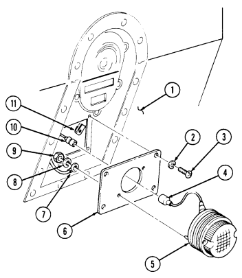
FOLLOW-ON TASKS: - Connect battery ground cable (para. 4-73).
· Check backup light operation (TM 9-2320-280-10).
4-96. Control Box Assembly Replacement (M997, M997A1, M997A2)
This task covers:
| Applicable Models |
|---|
| Tools |
| General mechanic's tool kit: |
Initial Setup:
automotive (Appendix B, Item 1) Materials/Parts Four lockwashers (Appendix G, Item 136) Locknut (Appendix G, Item 128) Lockwasher (Appendix G, Item 133) Two plain-assembled nuts (Appendix G, Item 201) Three lockwashers (Appendix G, Item 135) Two tiedown straps (Appendix G, Item 309) a. Removal b. Installation Equipment Condition Battery ground cable disconnected (para. 4-73).
| TM 9-2320-280-24P |
|---|
A. Removal
- Remove four screws (7), lockwashers (8), and cover (6) from control box (5). Discard lockwashers (8).
NOTE Prior to removal, tag leads for installation.
- Remove eight screws (4) and light harness leads (3) from terminal block (9) and mounting buss (10). 3. Disconnect light harness lead 791B (12) from NBC harness lead 791A (11).
Grommet must be removed through top of control box (5).
-
Remove grommet (2) and light harness (1) from control box (5). 5. Remove four screws (14) and four heating ventilating air conditioning leads (13) from mounting buss (10) and terminal block (9).
-
Remove plain-assembled nut (15), clamp (16), and heating ventilating air conditioning harness (17) from screw (18). Discard plain-assembled nut (15).
-
Remove nut (21) and ground cable (19) from ground stud (35). 8. Remove nut (24), lockwasher (23), washer (22), positive cable (27), and NBC cable (32) from power stud (34). Discard lockwasher (23).
-
Remove two screws (25) and NBC leads (26) from mounting buss (10).
-
Remove plain-assembled nut (29), NBC harness clamp (31), and power harness clamp (28) from stud (33). Discard plain-assembled nut (29).
4-96. CONTROL BOX ASSEMBLY REPLACEMENT (M997, M997A1, M997A2) (Cont'd)
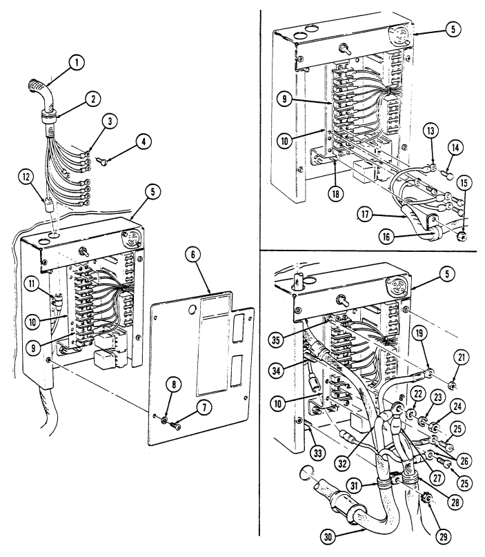
4-96. Control Box Assembly Replacement (M997, M997A1, M997A2) (Cont'D)
-
Remove two tiedown straps (14) and lead (12) from NBC harness (13). Discard tiedown straps (14). 12. Disconnect NBC harness leads 784A (5) and 784B (12) from heater leads (4). 13. Remove four capscrews (2) and washers (1) from NBC heater mounting plate (16) and body (15) and pull mounting plate (16) away for access to two capscrews (8).
-
Remove two nuts (6), capscrews (8), and ground terminals (7) from NBC heaters (3). 15. Remove screw (9), clamp (10), NBC harness (13), and A/C control box (11) from body (15). 16. Push grommet (40) down through hole in control box (17) and remove NBC harness (13) from control box (17).
-
Remove three screws (19), lockwashers (18), and control box (17) from body (37). Discard
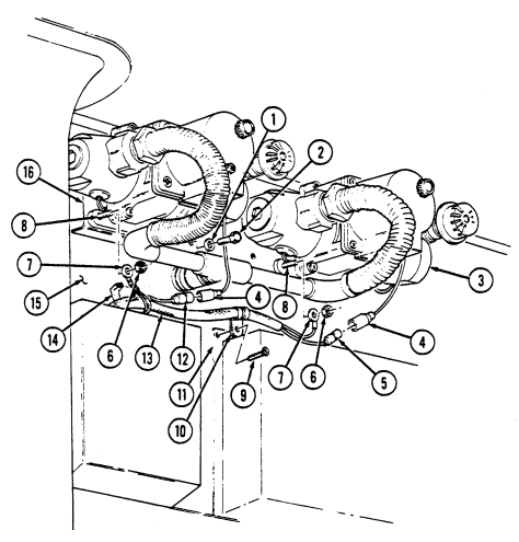
lockwashers (18).
4-96. Control Box Assembly Replacement (M997, M997A1, M997A2) (Cont'D)
b. Installation 1. Install control box (17) on body (37) with three lockwashers (18) and screws (19). 2. Install NBC harness (13) with grommet (40) up through hole in control box (17). 3. Install two ground terminals (7) from NBC harness (13) on heaters (3) with two capscrews (8) and nuts (6).
-
Install leads 791 and 794 (26) and 793 (29) on control box (17) with two capscrews (28). 5. Install NBC heater mounting plate (16) on body (15) with four washers (1) and capscrews (2). 6. Connect NBC harness leads 784A (5) and 784B (12) to heater leads (4). 7. Install lead (12) on NBC harness (13) with two tiedown straps (14). 8. Install NBC harness (13), power harness (32), and clamp (33) on screw (36) with plain-assembled nut (31). Connect NBC harness lead 791A (35) to light harness lead 791B (38).
-
Install positive cable (27) and NBC cable (34) on power stud (39) with washer (23), lockwasher (24), and nut (25).
-
Install ground cable (20) on ground stud (41) with nut (22).
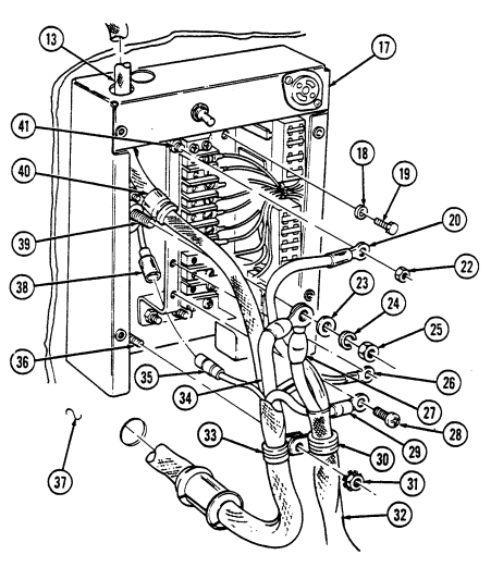
4-96. Control Box Assembly Replacement (M997, M997A1, M997A2) (Cont'D)
-
Install heating ventilating air conditioning harness (5) on screw (6) with clamp (4) and plain-assembled nut (3).
-
Install four control box leads (1) to mounting buss (7) and terminal block (8) with four screws (2). 13. Install light harness (9) down through hole in top of control box (13) and install grommet (10) in control box (13).
-
Connect light harness lead 791A (18) to NBC harness lead 791B (17). 15. Install eight light harness leads (11) on terminal block (8) and mounting buss (7) with eight screws (12).
-
Install cover (14) on control box (13) with four lockwashers (16) and screws (15).
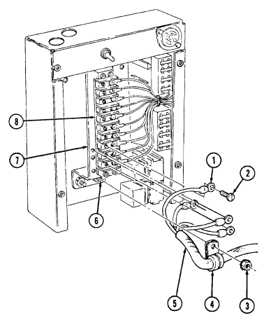
4-96. CONTROL BOX ASSEMBLY REPLACEMENT (M997, M997A1, M997A2) (Cont'd)
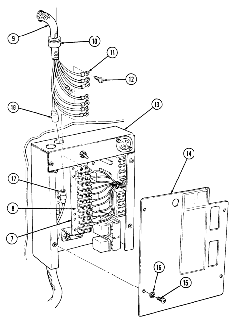
FOLLOW-ON TASK: Connect battery ground cable (para. 4-73).
4-97. Control Box Assembly Replacement (M996, M996A1)
This task covers:
Initial Setup:
| Applicable Models |
|---|
| M996, M996A1, M997, M997A1, M997A2 |
| Tools |
| General mechanic's tool kit: |
| automotive (Appendix B, Item 1) |
| Materials/Parts |
Four lockwashers (Appendix G, Item 136) Two plain-assembled nuts (Appendix G, Item 201) Three lockwashers (Appendix G, Item 135) Locknut (Appendix G, Item 128) Lockwasher (Appendix G, Item 133)
| TM 9-2320-280-10 |
|---|
| TM 9-2320-280-24P |
| Equipment Condition |
| - Rear steps lowered (TM 9-2320-280-10). |
| - Battery ground cable disconnected |
A. Removal B. Installation
a. Removal 1. Remove four screws (7), lockwashers (8), and cover (6) from control box (5). Discard lockwashers (8).
Prior to removal, tag leads for installation.
- Remove seven screws (4) and seven light harness leads (3) from terminal block (9). 3. Disconnect light harness lead 791B (11) from NBC harness lead 791A (10).
Grommet must be removed through top of control box.
-
Remove grommet (2) and light harness (1) from control box (5). 5. Remove plain-assembled nut (16), clamp (17), and heater harness (15) from mounting buss screw (18). Discard plain-assembled nut (16).
-
Remove three screws (14) and heater harness leads (13) from terminal block (9) and mounting buss (12).
4-97. Control Box Assembly Replacement (M996, M996A1) (Cont'D)
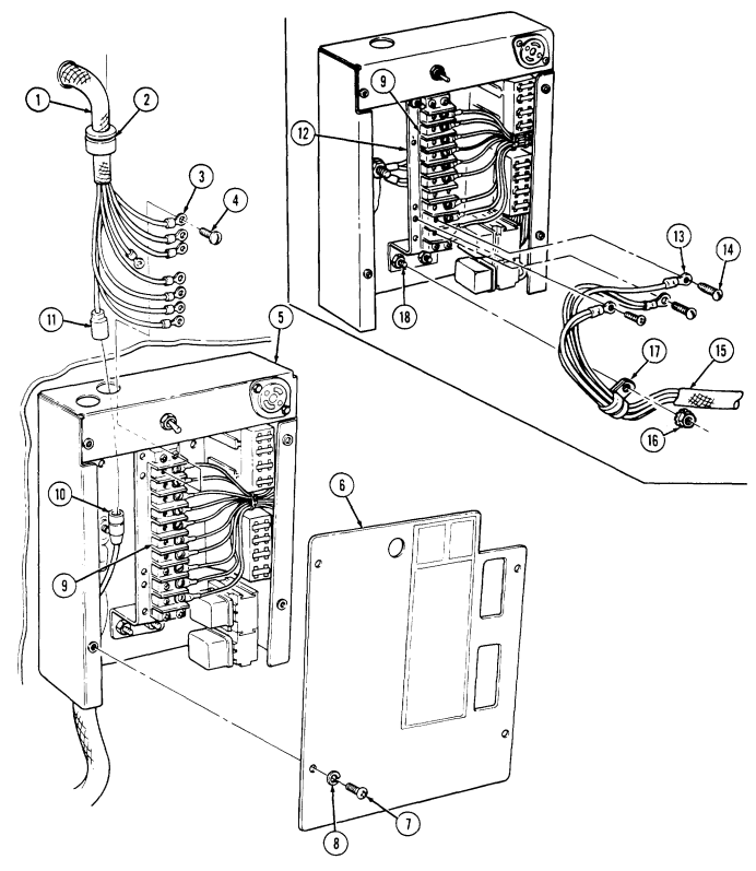
4-97. Control Box Assembly Replacement (M996, M996A1) (Cont'D)
- Remove power cable (9) from power stud (2) and clamp (16) from control box stud (17). 12. Remove three screws (5), lockwashers (4), and control box (1) from body (21).
Discard lockwashers (4).
B. Installation
-
Remove locknut (12), lockwasher (13), washer (11), NBC harness lead (10), and power cable (9) from positive stud (2). Discard lockwasher (13) and locknut (12).
-
Remove two screws (6) and two NBC harness leads (7) from mounting buss (8). 9. Remove plain-assembled nut (15), clamp (14), and NBC harness leads (7) and (10) from control box stud (17). Discard plain-assembled nut (15).
-
Remove nut (18) and negative cable (20) from mounting buss capscrew (3).
-
Install control box (1) on body (21) with three lockwashers (4) and screws (5). 2. Install negative cable (20) on mounting buss capscrew (3) with nut (18). 3. Install power cable (9) and NBC harness lead (10) on power stud (2) with washer (11), lockwasher (13), and locknut (12).
-
Install two NBC harness leads (7) on mounting buss (8) with two screws (6). 5. Install clamp (16) power cable (9), negative cable (20), clamp (14), and NBC harness leads (7) and (10), on control box stud (17) with plain-assembled nut (15).
4-97. Control Box Assembly Replacement (M996, M996A1) (Cont'D)
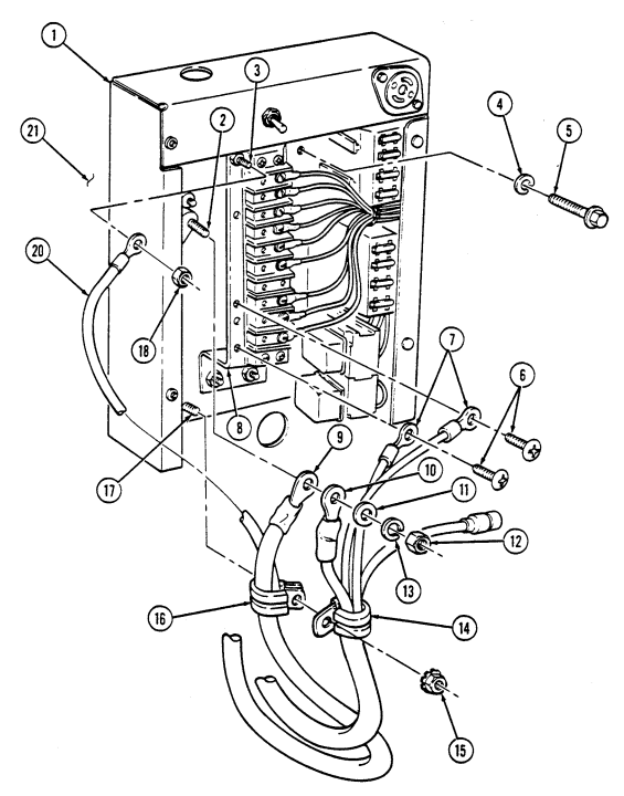
I
4-97. Control Box Assembly Replacement (M996, M996A1) (Cont'D)
-
Install three heater harness leads (3) to terminal block (2) and mounting buss (1) with three screws (4).
-
Install clamp (7) securing heater harness (6) to mounting buss screw (8) with plain-assembled nut (5).
-
Route light harness leads (11) and (18) through top of control box (13) and install grommet (9) and light harness (10) in control box (13).
-
Connect light harness lead 791B (18) to NBC harness lead 791A (17).
-
Install seven light harness leads (11) on terminal block (2) with seven screws (12). 11. Install cover (14) on control box (13) with four lockwashers (16) and screws (15).
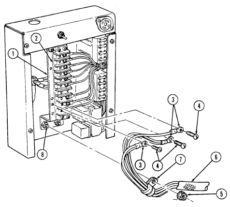
4-97. CONTROL BOX ASSEMBLY REPLACEMENT (M996, M996A1) (Cont'd)
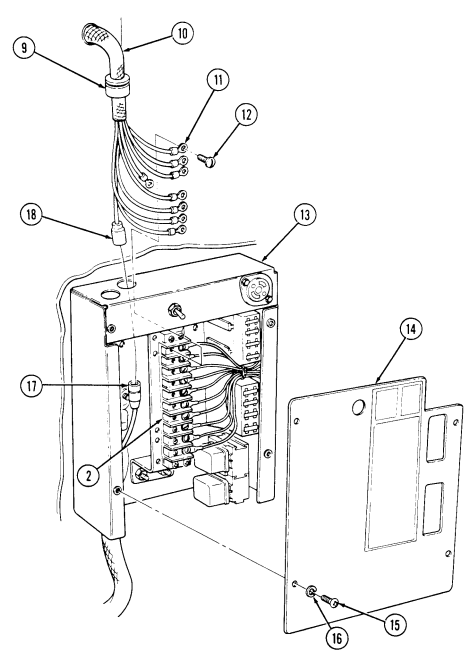
FOLLOW-ON TASKS: - Connect battery ground cable (para. 4-73).
· Check operation of spotlight (TM 9-2320-280-10).
4-98. Control Box Power Cables Replacement
This task covers:
Initial Setup:
Applicable Models M996, M996A1, M997, M997A1, M997A2 Tools General mechanic's tool kit: automotive (Appendix B, Item 1) Materials/Parts Four lockwashers (Appendix G, Item 136) Plain-assembled nut (Appendix G, Item 201) Lockwasher (Appendix G, Item 148) Lockwasher (Appendix G, Item 141) Lockwasher (Appendix G, Item 133) Locknut (Appendix G, Item 128) a. Removal b. Installation Manual References TM 9-2320-280-10 TM 9-2320-280-24P Equipment Condition Battery ground cable disconnected (para. 4-73).
Replacement of the control box power cables is basically the same for M996, M996A1, M997, M997A1, and M997A2 vehicles.
A. Removal
-
Remove four screws (6), lockwashers (5), and cover (7) from control box (1). Discard lockwashers (5). 2. Remove nut (4) and ground cable (2) from ground stud (18). 3. Remove locknut (12), lockwasher (13), washer (14), NBC harness cable (15), and positive cable (11) from power stud (17). Discard lockwasher (13) and locknut (12).
-
Remove plain-assembled nut (9), two clamps (10), power harness (8), and NBC harness (22) from screw (16). Discard plain-assembled nut (9).
Step 5 is for M997, M997A1, and M997A2 vehicles only.
- Remove two screws (20) two clamps (19) and power harness (8) from body (21) and remove clamps (19) from harness (8).
Steps 6 thru 8 apply to M996 and M996A1 vehicles only.
- Remove four screws (20), five clamps (19), and power harness (8) from body (21). Remove clamps (19) from harness (8).
4-98. CONTROL BOX POWER CABLES REPLACEMENT (Cont'd)
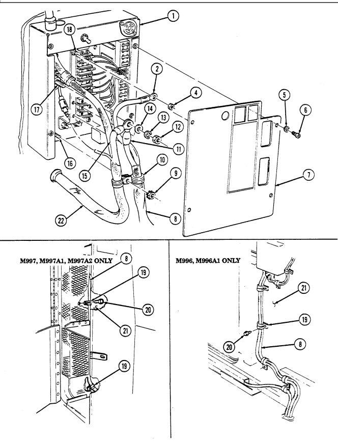
4-98. Control Box Power Cables Replacement (Cont'D)
Remove two screws (1) and three clamps (3) from power harness (8), resuscitator harness (2) and body (6).
Remove screw (1) and clamps (3) and (7) from body (6) and power harness (8). Remove grommets (4) and (9), power harness (8), and resuscitator harness (2) from floor (5) and body (6).
Remove grommet (23) from battery box (20). Remove capscrew (10), lockwasher (11), ground cable (13), and two cables (12) from shunt (16) Discard lockwasher (11).
Remove two screws (14), clamps (17), and positive cable (15) from battery box (20).
Remove nut (22), lockwasher (21), two battery cables (19), and positive cable (15) from power stud (18) . Discard lockwasher (21).
Remove power harness (8) from vehicle.
B. Installation
Route power harness (8) in approximate mounting location in vehicle.
Install positive cable (15) and two battery cables (19) on power stud (18) with lockwasher (21) and nut (22).
Install two clamps (17) on positive cable (15) and battery box (20) with two screws (14). Install ground cable (13) and two cables (12) on shunt (16) with lockwasher (11) and capscrew (10).
Install grommet (23) on power harness (8) in battery box (20).
Steps 6 thru 8 apply to M996 and M996A1 vehicles only.
Install clamp (7), power harness (8), and resuscitator harness clamp (3) on body (6) with screw (1). Install three clamps (3), power harness (8), resuscitator harness (2), on body (6) with two screws (1). Install power harness (8) and resuscitator harness (2) with two grommets (4) and (9) in floor (5) and body (6).
4-98. Control Box Power Cables Replacement (Cont'D)
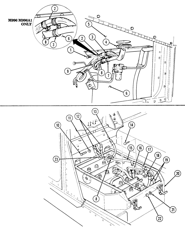
4-98. Control Box Power Cables Replacement (Cont'D)
-
Install positive cable (15) and NBC harness cable (16) on control box power stud (18) with washer (8), lockwasher (9), and locknut (10).
-
Install ground cable (2) on ground stud (19) with nut (4). 11. Install two clamps (11), power harness (13), and NBC harness (14) on screw (17) with plainassembled nut (12).
-
Install cover (7) on control box (1) with four lockwashers (5) and screws (6). 13. Install two clamps (22) and power harness (13) on body (21) with two screws (20).
NOTE
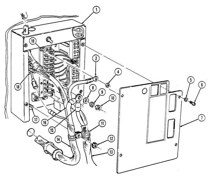
Step 14 applies to M996 and M996A1 vehicles only.
- Install five clamps (22) and power harness (13) on body (21) with four screws (20).
4-98. Control Box Power Cables Replacement (Cont'D)
M996, M996A1 ONLY
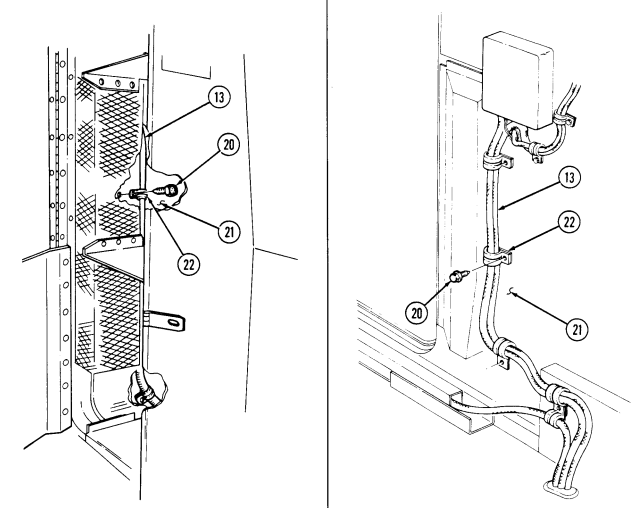
FOLLOW-ON TASKS: - Connect battery ground cable (para. 4-73).
- Check control box operation (TM 9-2320-280-10).
4-99. Nbc Control Box And Wiring Harness Replacement (M996, M996A1)
This task covers:
A. Removal B. Installation
| Materials/Parts |
|---|
| M996, M996A1, M997, M997A1, M997A2 |
|---|
| Tools |
| General mechanic's tool kit: |
| automotive (Appendix B, Item 1) |
Initial Setup:
Four lockwashers (Appendix G, Item 136) Plain-assembled nut (Appendix G, Item 201) Locknut (Appendix G, Item 128) Three locknuts (Appendix G, Item 97) Lockwasher (Appendix G, Item 133) Three lockwashers (Appendix G, Item 135) Five tiedown straps (Appendix G, Item 309) NBC control panel removed (para. 4-124).
a. Removal
| TM 9-2320-280-10 | TM 9-2320-280-24P |
|---|---|
| Equipment Condition |
- Remove four screws (11), lockwashers (10), and cover (9) from control box (1). Discard lockwashers (10).
Prior to removal, tag all leads for installation.
-
Remove locknut (12), lockwasher (3), washer (2), and positive cable lead 782 (22) from positive stud (25). Discard lockwasher (3) and locknut (12).
-
Remove two screws (13) and NBC harness leads (14) from mounting buss (26). 4. Disconnect lead 791A (23) from light harness lead 791B (24). 5. Remove plain-assembled nut (18), clamp (20), and NBC harness (4) from control box stud (21). Discard plain-assembled nut (18).
-
Remove four screws (8), clamps (7), NBC harness (4), and heater harness (6) from body (5). 7. Remove two screws (15), washers (16), retainer (17), and grommet (19) from body (5) and remove retainer (17) and grommet (19) from NBC harness (4).
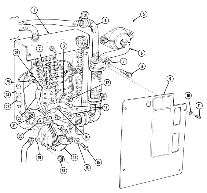
4-99. NBC CONTROL BOX AND WIRING HARNESS REPLACEMENT (M996, M996A1) Cont'd)
4-99. Nbc Control Box And Wiring Harness Replacement (M996, M996A1) Cont'D)
-
Remove four screws (4) and harness channel (5) from body (6). Pull channel (5) away from body (6).
-
Remove three tiedown straps (8). Discard tiedown straps (8).
-
Disconnect lead 785B (9), lead 785A (10), and lead 786A (19) from NBC heaters (7). 11. Remove three capscrews (17), lockwashers (16), and ground leads (18) from NBC heaters (7).
Discard lockwashers (16).
-
Remove screw (1), clamp (2), and harness (3) from body (6). 13. Remove two screws (14), washers (13), grommet (11), retainer (15), and intercom cable (12) from body (6).
-
Remove three screws (25), clamps (26), and harness (3) from body (27). Remove clamps (26). 15. Remove locknut (24), washer (21), capscrew (20), washer (21), clamp (22), and harness (3) from body (27).
-
Remove two locknuts (32), washer (33), capscrew (35), washer (33), and leads 795B (36) and 795C (34) from body (27).
-
Remove screw (31) and ground (29) from NBC heaters and filter assembly (28). 18. Disconnect connector (30) from NBC heater and filter assembly (28). 19. Remove grommet (23) and harness (3) from body (27).
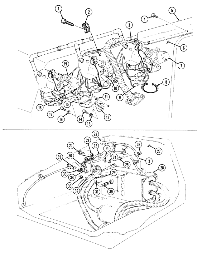
4-99. NBC CONTROL BOX AND WIRING HARNESS REPLACEMENT (M996, M996A1) Cont'd)
4-99. Nbc Control Box And Wiring Harness Replacement (M996, M996A1) Cont'D)
-
Remove two tiedown straps (11) from leads (12) and (13) and harness (8). Discard tiedown straps (11). 21. Disconnect leads 787A (12) and 786B (13) from NBC heaters (10). 22. Remove screw (15), clamp (14), and harness (8) from body (9). 23. Remove two screws (5) and cover (6) from bracket (16). 24. Pull cover (6) away from switch (1) to allow access to leads. 25. Remove two screws (3) and leads (2) and (4) from switch (1).
-
Pull leads (2) and (4) through grommet (7) in cover (6).
Use care when removing harness. Failure to do so will cause damage to harness.
- Remove harness (8) from vehicle.
b. Installation
Use care when routing harness. Failure to do so will cause damage to harness.
Route leads (2) and (4) through grommet (7) in cover (6). Route harness (8) in approximate mounting location. Connect leads (2) and (4) to switch (1) with two screws (3). Install cover (6) to bracket (16) with two screws (5). Install clamp (14) and harness (8) on body (25) with screw (15).
Connect leads 787A (12) and 786B (13) to NBC heaters (10).
Install two tiedown straps (11) on leads (12) and (13) and harness (8).
Install grommet (22) on harness (8) in body (25).
Install clamp (20) and harness (8) on body (25) with washer (19), capscrew (18), washer (19), and nut (21). Install leads 795B (17) and 795C (32) on body (25) with two washers (31), capscrews (33), washers (31), and nuts (30). Install three clamps (24) on harness (8) to body (25) with three screws (23). Install ground (27) on NBC heater and filter assembly (26) with screw (29).
Connect harness (28) to NBC heater and filter assembly (26).
4-99. NBC CONTROL BOX AND WIRING HARNESS REPLACEMENT (M996, M996A1) Cont'd)
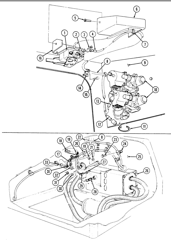
4-99. Nbc Control Box And Wiring Harness Replacement (M996, M996A1) Cont'D)
-
Install grommet (12), retainer (11), harness (3), and intercom cable (13) to body (7) with two washers (14) and screws (15).
-
Install clamp (2) and harness (3) on body (7) with screw (1). 16. Install ground leads (16) on three NBC heaters (6) and body (7) with three lockwashers (17) and capscrews (18).
-
Connect lead 785A (9), lead 785B (10), and lead 786A (19) to NBC heaters (6). 18. Install three tiedown straps (8) on leads (9), (10), and (19), and harness (3). 19. Install harness channel (4) over harness (3) on body (7) with four screws (5). 20. Install four clamps (25) on harness (3) and heater harness (24) on body (23) with four screws (26). 21. Install positive lead 782 (40) on power stud (43) with washer (21), lockwasher (22), and locknut (30).
-
Install two NBC harness leads (32) on mounting buss (44) with two screws (31). 23. Connect lead 791A (41) to light harness lead 791B (42). 24. Install clamp (38) on NBC harness (3) and control box stud (39) with plain-assembled nut (36). 25. Install grommet (37) and retainer (35) on NBC harness (3) and body (23) with two washers (34) and screws (33).
-
Install cover (27) on control box (20) with four lockwashers (28) and screws (29).

4-99. NBC CONTROL BOX AND WIRING HARNESS REPLACEMENT (M996, M996A1) Cont'd)
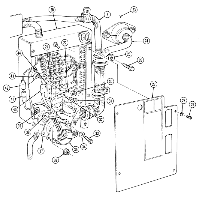
FOLLOW-ON TASK: NBC control panel installed (para. 4-124).
4-100. Nbc Control Box And Wiring Harness Replacement (M997, M997A1, M997A2)
This task covers:
Initial Setup:
Applicable Models M997, M997A1, M997A2 Tools General mechanic's tool kit: automotive (Appendix B, Item 1) Materials/Parts Locknut (Appendix G, Item 77) Four lockwashers (Appendix G, Item 136) Five lockwashers (Appendix G, Item 135) Three assembled locknuts (Appendix G, Item 130) Five plain-assembled nuts (Appendix G, Item 201) Nine tiedown straps (Appendix G, Item 309)
A. Removal B. Installation
Manual References TM 9-2320-280-10 TM 9-2320-280-24P Equipment Condition
- Control panel removed (para. 4-124). - Front cover panel removed (para. 11-187).
Use care when removing harness. Failure to do so will cause damage to harness.
A. Removal
- Remove four screws (8) lockwashers (7) and cover (6) from control box (1). Discard lockwashers (7). 2. Remove assembled locknut (11), clamp (12), and NBC harness (13) from control box stud (16).
Discard assembled locknut (11).
Prior to removal, tag leads for installation.
- Remove nut (5), washer (3), and lead 782 (2) from power stud (20). 4. Disconnect NBC harness lead 791A (17) from light harness lead 791B (18). 5. Remove two screws (9) and NBC harness leads (10) from mounting buss (19). 6. Remove grommet (21) by pushing down through top of control box (1). 7. Remove grommet (14) and NBC harness (13) from body (15).
4-100. NBC CONTROL BOX AND WIRING HARNESS REPLACEMENT (M997, M997A 1, M997A2) (Cont'd)
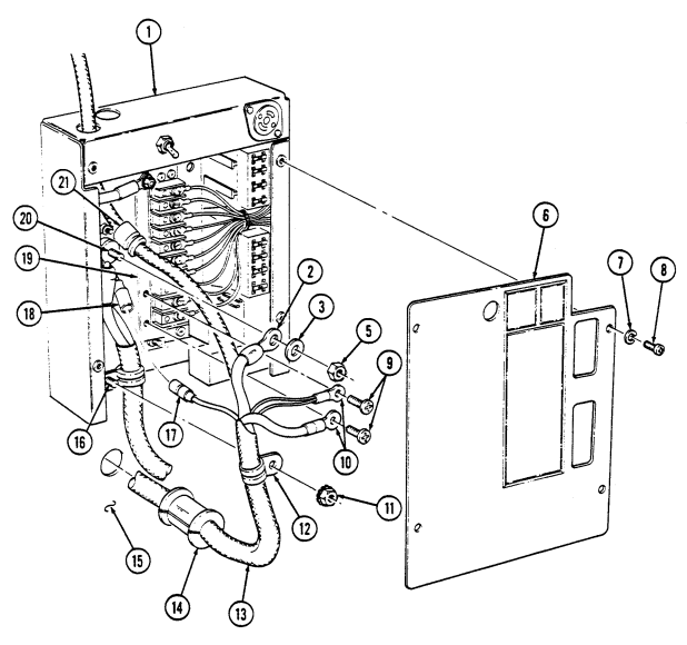
4-100. Nbc Control Box And Wiring Harness Replacement (M997, M997A1, M997A2) (Cont'D)
- Remove two tiedown straps (6). Disconnect leads 784A (4) and 784B (12) from NBC heaters (1).
Discard tiedown straps (6).
-
Remove four capscrews (3), washers (2), and mounting bracket (16) from body (14). Pull bracket (16) and NBC heaters (1) away from body (14) to allow access to ground leads (5) hardware.
-
Remove nut (13), capscrew (15), and ground terminals (5) from NBC heaters (1). 11. Remove screw (9), lockwasher (10), clamp (11), and harness (7) from A/C control box (8) and body (14). Remove clamp (11). Discard lockwasher (10).
-
Route harness (7) through body (14) into cab. 13. Remove two screws (26), clamps (25) and harness (7) from body (21). 14. Disconnect harness lead 785A (35) from NBC heater lead (36). 15. Remove nut (29), washer (30), capscrew (32), washer (30), and leads 796 and 796A (31) from NBC heater (33).
-
Remove five screws (27), clamps (28), harness (7), and intercom cable (24) from body (21). Remove clamps (28).
-
Remove tiedown straps (19) and (34). Disconnect harness lead 786A (40) from NBC heater lead (41). Discard tiedown straps (19) and (34).
-
Remove locknut (43), washer (17), capscrew (18), washer (17), and leads 796B and 796A (42) from
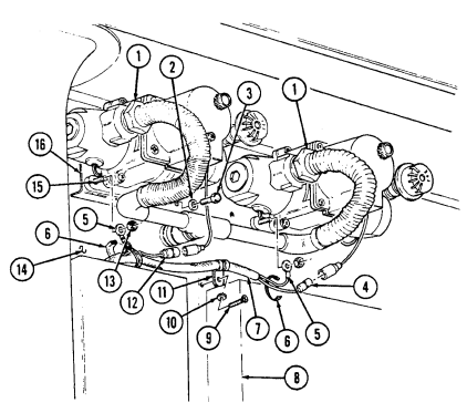
NBC heater (44). Discard locknut (43).
- Remove two assembled locknuts (20), capscrews (37), washers (38), clamp (39), grommet (22), retainer (23), harness (7), and intercom cable (24) from body (21). Discard assembled locknuts (20).
4-100. NBC CONTROL BOX AND WIRING HARNESS REPLACEMENT (M997, M997A1, M997A2) (Cont'd)
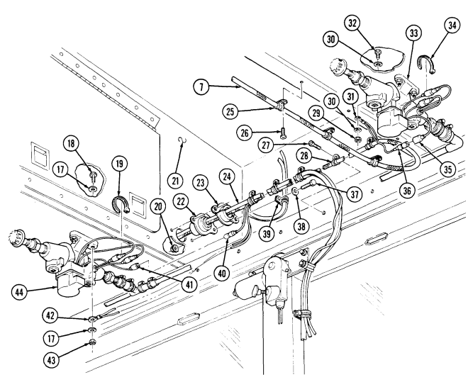
4-100. Nbc Control Box And Wiring Harness Replacement (M997, M997A1, M997A2) (Cont'D)
- Remove three plain-assembled nuts (19), screws (13), and cover (18) from body (14).
Discard plain-assembled nuts (19).
-
Remove two screws (20), clamps (21), harness (11), and intercom cable (12) from body (14). 22. Remove screw (7) and lead (9) from heater and filter assembly (10). 23. Remove two plain-assembled nuts (17), screws (15), clamps (16), harness (11), and intercom cable (12) from body (14). Discard plain-assembled nuts (17).
-
Disconnect connector (8) from heater and filter assembly (10). 25. Remove grommet (23) and harness (11) from body (14). 26. Remove screw (25), clamp (24), and harness (11) from body (14). 27. Remove two screws (5) and cover (26) from bracket (4). Pull cover (26) away from switch (3) to allow access to leads.
-
Remove two screws (27) and leads (2) and (6) from switch (3). 29. Remove harness (11) from grommet (22) and route harness (11) through opening in body (14). 30. Remove two screws (39), washers (38), retainer (37), grommet (36), harness (11), and intercom cable (12) from body (14).
-
Remove six tiedown straps (40) from NBC heater leads (34) and harness (11). Discard tiedown straps (40).
-
Disconnect leads 786B (45), 787A (44), and 787B (41) from NBC connectors (42). 33. Remove four screws (28), lockwashers (29), washers (30), and mounting bracket (31) from brackets (32).
Pull bracket (31) away from body (14) to allow access to ground leads hardware. Discard lockwashers (29).
- Loosen three hose clamps (49) and pull heaters (47) from fittings (48). 35. Remove three nuts (35) and ground leads (34), (43), and (46) from capscrews (33). 36. Remove harness (11) from vehicle.
b. Installation
Use care when routing harness. Failure to do so will cause damage to harness.
-
Route harness (11) through vehicle in approximate mounting location. 2. Install leads (34), (43), and (46) on three capscrews (33) with nuts (35).
-
Install cover (26) over switch (3) on bracket (4) with two screws (5). 11. Install clamp (24) and harness (11) on body (14) with screw (25).
-
Connect three heaters (47) to fittings (48) and tighten clamps (49). 4. Install mounting bracket (31) to brackets (32) with four washers (30), lockwashers (29), and screws (28).
-
Connect leads 786B (45), 787A (44), and 787B (41) to NBC heater connectors (42). 6. Install six tiedown straps (40) on NBC heater leads (34) and harness (11). 7. Install grommet (36), retainer (37), harness (11), and intercom cable (12) on body (14) with washers (38) and screws (39).
-
Route harness (11) through grommet (22) and opening in body (14). 9. Install leads (2) and (6) on switch (3) with two screws (27).
4-100. NBC CONTROL BOX AND WIRING HARNESS REPLACEMENT (M997, M997A1,
M997A2) (Cont'D)
Install grommet (23) and harness (11) in body (14).
Connect connector (8) on heater and filter assembly (10).
Install lead (9) to heater and filter assembly (10) with screw (7).
Install two clamps (16), harness (11), and intercom cable (12) to body (14) with two screws (15) and 15.
plain-assembled nuts (17).
Install two clamps (21), harness (11), and intercom cable (12), on body (14) with two screws (20).
Install cover (18) over harness (11) and intercom cable (12), and to body (14) with three screws (13) 17.
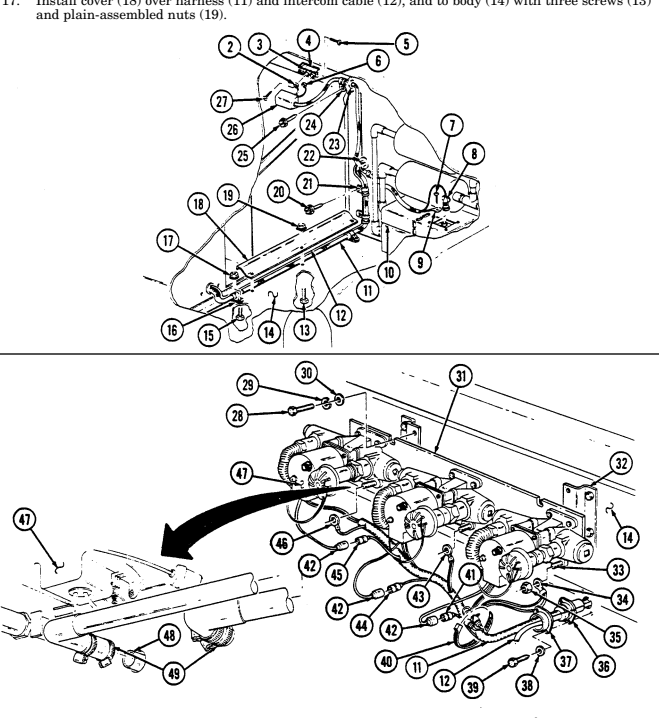
4-100. Nbc Control Box And Wiring Harness Replacement (M997, M997A1, M997A2) (Cont'D)
-
Install grommet (6), retainer (7), harness (9), and intercom cable (8) on body (5) with clamp (24), two washers (23), capscrews (22), and assembled locknuts (4).
-
Install leads 796B and 796A (27) on NBC heater (29) with washer (1), capscrew (2), washer (1), and locknut (28).
-
Connect harness lead 786A (25) to NBC heater lead (26). 21. Install five clamps (13), harness (9), and intercom cable (8) on body (5) with five screws (12). 22. Install leads 796 and 796A (16) on NBC heater (18) with washer (15), capscrew (17), washer (15), and nut (14).
-
Connect harness lead 785A (21) on NBC heater lead (20). 24. Install two clamps (10) on harness (9) and body (5) with three screws (11). 25. Install tiedown straps (3) and (19) securing heater leads together. 26. Install clamp (42) and harness (9) on A/C control box (40) and body (47) with lockwasher (41) and screw (38).
-
Install two ground terminals (37) on NBC heaters (30) and bracket (48) with capscrews (39) and (49) and nuts (35) and (46).
-
Install bracket (48) and NBC heaters (30) on body (47) with four washers (31) and capscrews (32). 29. Connect leads 784A (36) and 784B (44) on NBC heater leads (34) and (43). 30. Install two tiedown straps (45) on harness (9) and leads.
4-100. NBC CONTROL BOX AND WIRING HARNESS REPLACEMENT (M997, M997A1, M997A2) (Cont'd)
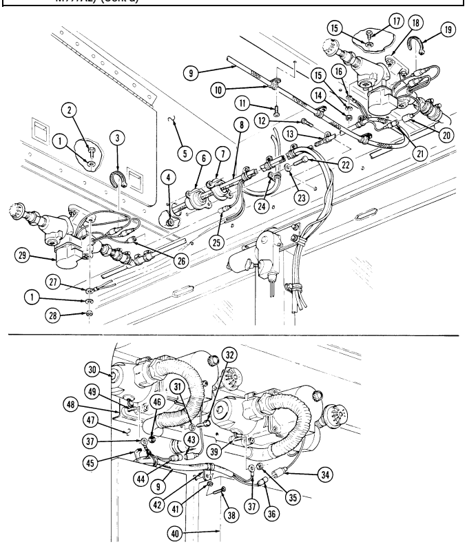
4-100. Nbc Control Box And Wiring Harness Replacement (M997, M997A1, M997A2) (Cont'D)
- Install grommet (21) through top of control box (1) to secure NBC harness (13). 32. Install lead 782 (2) on power stud (20) with washer (3) and nut (5). 33. Connect NBC harness lead 791A (17) to light harness lead 791B (18). 34. Install two NBC harness leads (10) on mounting buss (19) with two screws (9). 35. Install clamp (12) and NBC harness (13) on control box stud (16) with assembled locknut (11). 36. Install cover (6) on control box (1) with four lockwashers (7) and screws (8). 37. Install grommet (14) in body (15) to secure NBC harness (13).
4-100. NBC CONTROL BOX AND WIRING HARNESS REPLACEMENT (M997, M997A I, M997A2) (Cont'd)
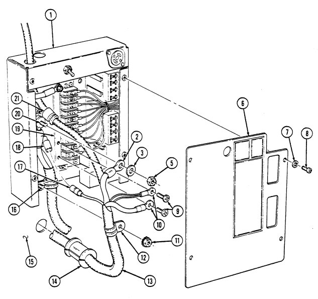
FOLLOW-ON TASKS: - Install control panel (para. 4-124).
- Install front cover panel (para. 11-187).
4-101. Interior Lighting Harness Assembly Replacement (M997, M997A1, M997A2)
This task covers:
a. Removal b. Installation
| INITIAL SETUP: | |
|---|---|
| Applicable Models | Manual References |
| M996, M996A1, M997, M997A1, M997A2 | TM 9-2320-280-10 |
| TM 9-2320-280-24P | |
| Tools | |
| General mechanic's tool kit: | Equipment Condition |
| automotive (Appendix B, Item 1) | Battery ground cable disconnected (para. 4-73). |
| Materials/Parts | |
| Four lockwashers (Appendix G, Item 136) |
a. Removal 1. Remove four screws (4), lockwashers (5), and cover (3) from control box (6). Discard lockwasher (5).
Prior to removal, tag leads for installation.
-
Remove eight screws (2) and lighting harness leads (1) from terminal block (7) and mounting buss (9).
-
Remove two screws (13), clamps (14), and lighting harness (12) from duct (15). 4. Disconnect lead 791B (10) from NBC harness lead 791A (8). 5. Remove grommet (11) and harness (12) from control box (6). 6. Deleted. 7. Remove four screws (29), clamp (17.1), and channel (30) from body (19) and pull channel (30) away for access to clamp (25).
-
Remove nut (23), screw (26), two clamps (25), and light harnesses (20) from cover (30). 9. Remove ten screws (21), cover (28), clamp (16), and harness (12) from body (19). Lower cover (28) to allow access to harness (12).
-
Disconnect six harness leads (17) from light leads (24). Remove harness cover (28) and grommet (27) from cover (28).
-
Disconnect four harness leads (18) from light leads (22).
4-101. INTERIOR LIGHTING HARNESS ASSEMBLY REPLACEMENT (M997, M997A1,
M997A2) (Cont'd)
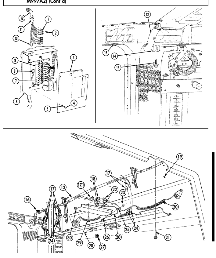
4-101. Interior Lighting Harness Assembly Replacement (M997, M997A1, M997A2) (Cont'D)
-
Remove seven screws (1) and clamps (2) from harness (3) and body (4). 13. Remove two screws (15) and clamps (14) from harness (3) and body (4). 14. Remove two grommets (13) from harness (3) and body (4). 15. Remove four screws (19) and lockwashers (18) from backup light cover (17) and body (16). Pull cover (17) away from body (16) to allow access to harness (3). Discard lockwashers (18).
-
Disconnect harness lead 21H (21) from light harness 21G (20). 17. Remove grommet (12) and harness (3) from body (4). 18. Remove screw (5) and clamp (11) from harness (3) and body (4). 19. Remove two nuts (8), screws (6), and clamps (7) from harness (3) and body (4). Discard nuts (8). 20. Disconnect two harness leads (10) from blackout switch leads (9). 21. Remove six screws (23) and clamps (22) from harness (3) and body (24).
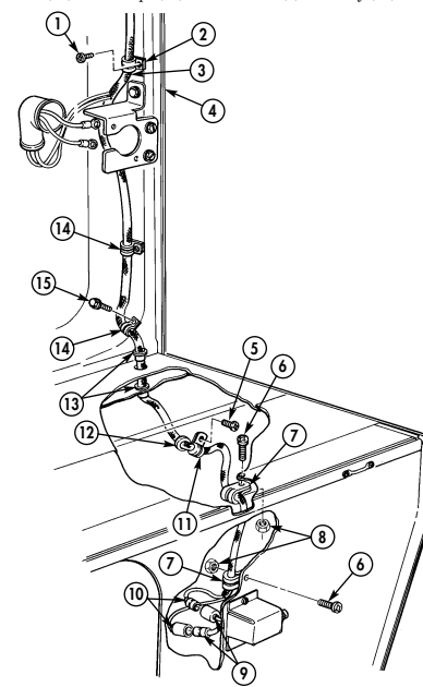
4-101. INTERIOR LIGHTING HARNESS ASSEMBLY REPLACEMENT (M997, M997A1, M997A2 (Cont'd)
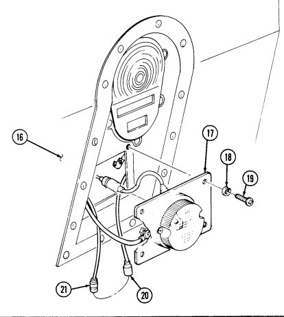
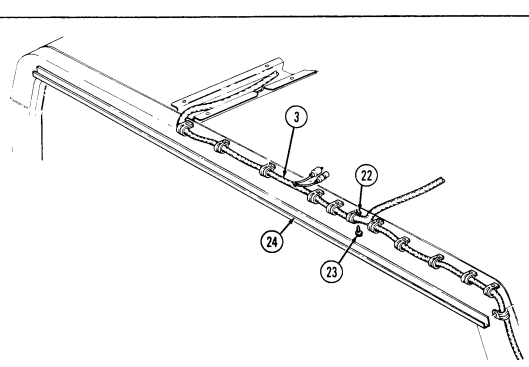
4-101. Interior Lighting Harness Assembly Replacement (M997, M997A1, M997A2) (Cont'D)
- Remove four screws (7) from cover (6) and body (14). 23. Remove nut (3), screw (10), and cover (6) from two clamps (11) and light harnesses (11.1). 24. Disconnect four harness leads (5) from light leads (4). 25. Remove ten screws (13) from cover (8) and body (14). Lower cover (8) to allow access to harness (1). 26. Disconnect six harness leads (2) from light harness leads (12). Remove grommet (9) and harness cover (8).
Use care when removing harness. Failure to do so will cause damage to harness.
- Remove harness (1) from body (14).
b. Installation
Use care when routing harness. Failure to do so will cause damage to harness.
-
Route harness (1) through vehicle in approximate mounting location. 2. Position harness cover (8) over harness (1) and connect six harness leads (2) to light harness leads (12). Install grommet (9) and cover (8) to body (14) with ten screws (13).
-
Connect four harness leads (5) to light leads (4). 4. Install two clamps (11) and light harnesses (11.1) on cover (6) with screw (10) and nut (3). 5. Install cover (6) on body (14) with four screws (7). 6. Install six clamps (15) on harness (1) and body (17) with six screws (16).
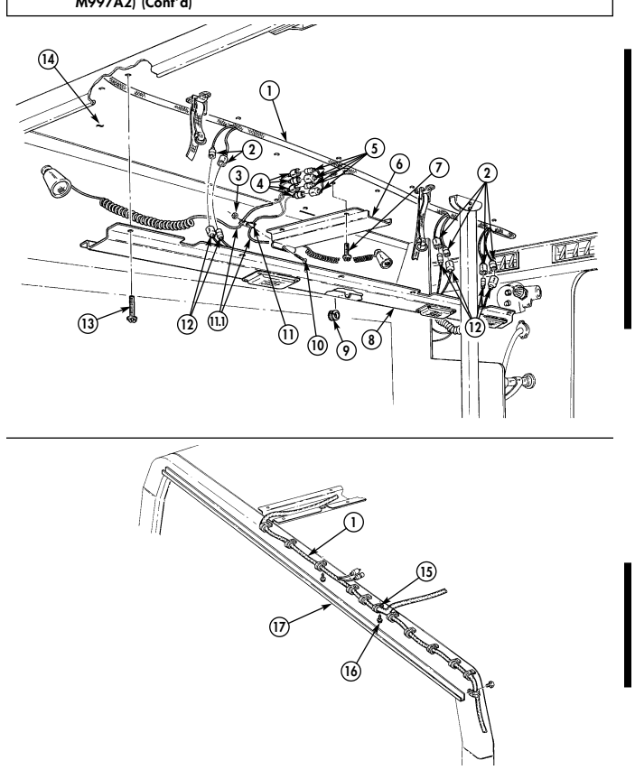
4-101. INTERIOR LIGHTING HARNESS ASSEMBLY REPLACEMENT (M997, M997A1, M997A2) (Cont'd)
4-101. Interior Lighting Harness Assembly Replacement (M997, M997A1, M997A2) (Cont'D)
-
Connect two harness leads (9) to blackout switch leads (8). 8. Install two clamps (10) on harness (3) and body (4) with two screws (6) and nuts (7). 9. Install clamp (11) on harness (3) and body (4) with screw (5).
-
Install grommet (12) and harness (3) in body (4). 11. Connect harness lead 24H (21) to lead 21G (20). 12. Install backup light cover (17) on body (16) with four lockwashers (18) and screws (19). 13. Install two grommets (13) on harness (3) and body (4). 14. Install two clamps (14) on harness (3) and body (4) with two screws (15). 15. Install seven clamps (2) on harness (3) and body (4) with seven screws (1).
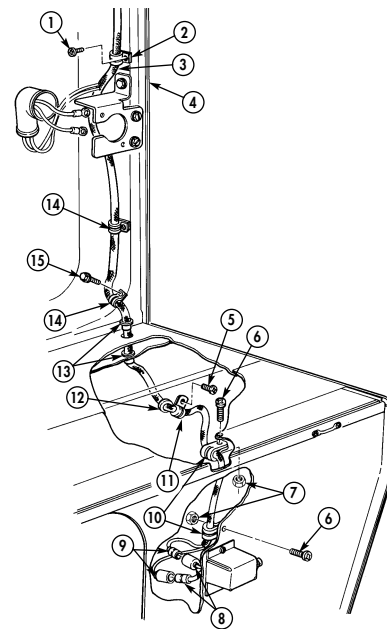
4-101. INTERIOR LIGHTING HARNESS ASSEMBLY REPLACEMENT (M997, M997A1, M997A2) (Cont'd)
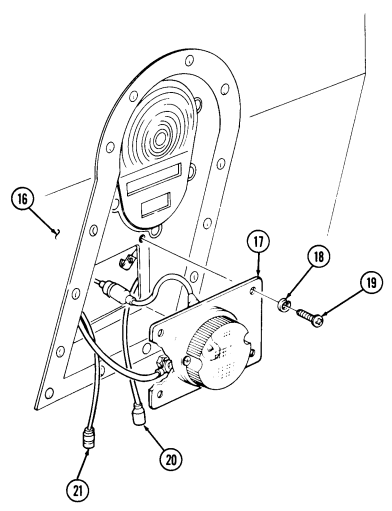
4-101. Interior Lighting Harness Assembly Replacement (M997, M997A1, M997A2) (Cont'D)
-
Connect four harness leads (4) to light harness leads (6). 17. Install grommet (13.1) on cover (14) and connect six harness leads (1) and (5) to light leads (16) and (11).
-
Install clamp (17) and cover (14) on body (8) and harness (2) with ten screws (10). 19. Install two clamps (12) on light harnesses (9) and cover (3) with screw (13) and nut (7). 20. Install cover (3) and clamp (3.1) on body (8) with four screws (15). 21. Deleted. 22. Install two clamps (21) on harness (2) and duct (20) with two screws (22). 23. Connect lead 791B (32) to NBC harness lead 791A (30). 24. Install eight leads (23) on terminal block (29) and ground buss (31) with eight screws (24). 25. Install grommet (33) on control box (28). 26. Install cover (25) on control box (28) with four screws (26) and lockwashers (27).
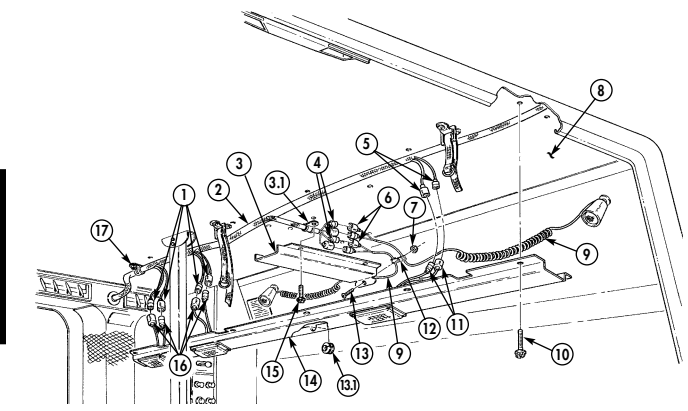
4-101. INTERIOR LIGHTING HARNESS ASSEMBLY REPLACEMENT (M997, M997A1, M997A2) (Cont'd)
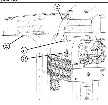
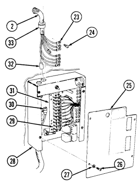
FOLLOW-ON TASKS: - Connect battery ground cable (para. 4-73).
· Check operation of interior dome lights (TM 9-2320-280-10).
- Install rear door blackout switch (para. 4-93).
· Install electrical outlet/bracket (para. 4-90).
4-102. Interior Lighting Harness Assembly Replacement (M996, M996A1)
| This task covers: | |
|---|---|
| a. Removal | b. Installation |
| INITIAL SETUP: | |
| Applicable Models | Manual References |
| M997, M997A1, M997A2 | TM 9-2320-280-24P |
| Tools | Equipment Condition |
| General mechanic's tool kit: | Battery ground cable disconnected |
| automotive (Appendix B, Item 1) | (para. 4-73). |
| Materials/Parts | |
| Four lockwashers (Appendix G, Item 136) | |
| Locknut (Appendix G, Item 128) | |
| Lockwasher (Appendix G, Item 133) | |
| Two plain-assembled nuts |
A. Removal
- Remove four screws (4), lockwashers (5), and cover (3) from control box (6). Discard lockwasher (5).
Prior to removal, tag leads for installation.
-
Remove eight screws (2) and lighting harness leads (1) from terminal block (7) and mounting buss (9).
-
Disconnect lead 791B (10) from NBC harness lead 791A (8). 4. Remove grommet (12) and harness (11) from control box (6). 5. Remove four screws (14) and cover (13) from body (15) and harness (11). 6. Remove grommet (16) from harness (11). 7. Remove four screws (18) and cover (17) from body (15). 8. Remove four screws (30) and clamp (19.1) from channel (31) and body (15). 9. Remove nut (23), screw (28), clamp (27), and light harness (24) from cover (31).
-
Remove grommet (28.1) from cover (29). 11. Remove ten screws (25) from cover (29) and body (15). Lower cover (29) to allow access to harness (11).
-
Disconnect six harness leads (21) from light leads (26). Remove harness cover (29). 13. Disconnect two harness leads (20) from light leads (22).
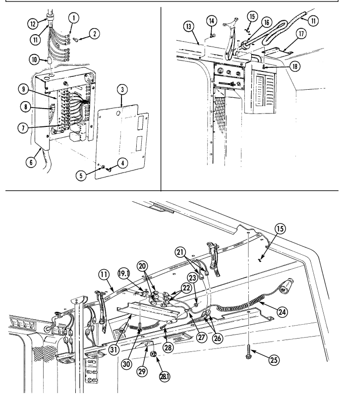
4-102. INTERIOR LIGHTING HARNESS ASSEMBLY REPLACEMENT (M996, M996A1) (Cont'd)
4-102. Interior Lighting Harness Assembly Replacement (M996, M996A1) (Cont'D)
-
Remove seven screws (1) and clamps (3) from harness (2) and body (4). 15. Remove two screws (15) and clamps (14) from harness (2) and body (4). 16. Remove two grommets (13) from harness (2) and body (4). 17. Remove four screws (19) and lockwashers (18) from backup light cover (17) and body (16). Pull cover (17) away from body (16) to allow access to harness (2). Discard lockwashers (18).
-
Disconnect harness lead 21H (21) from light harness 21G (20). 19. Remove grommet (12) from harness (2) and body (4). 20. Remove screw (5) and clamp (6) from harness (2) and body (4). 21. Remove two nuts (11), screws (8), and clamps (7) from harness (2) and body (4) 22. Disconnect two harness leads (10) from blackout switch leads (9). 23. Remove six screws (23) and clamps (22) from harness (2) and body (24).
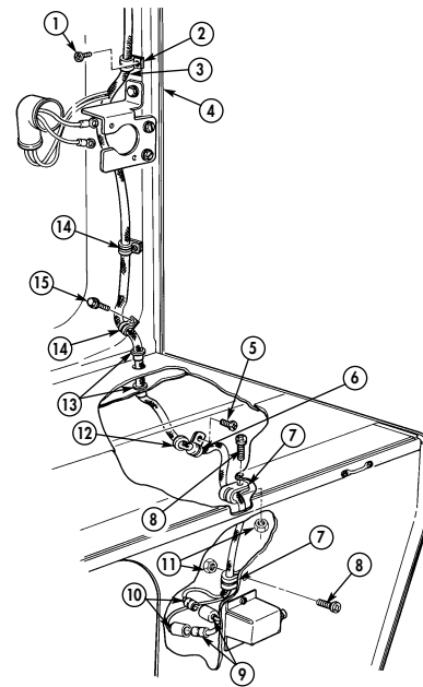
4-102. INTERIOR LIGHTING HARNESS ASSEMBLY REPLACEMENT (M996, M996A1) (Cont'd)
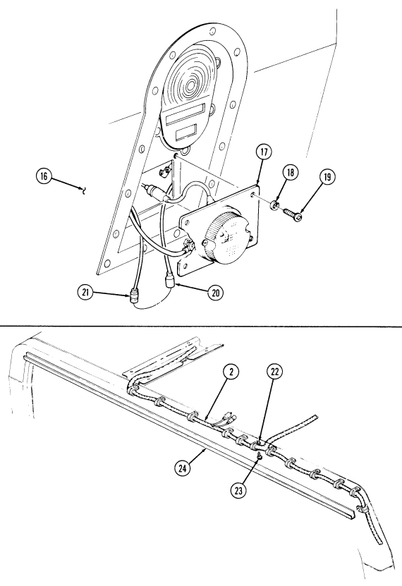
4-102. Interior Lighting Harness Assembly Replacement (M996, M996A1) (Cont'D)
- Remove four screws (7) from cover (6) and body (15). 25. Remove nut (3), screw (10), clamp (11), and cover (6) from light harness (14). 26. Remove grommet (9) from cover (8). 27. Disconnect two harness leads (5) from light leads (4). 28. Remove ten screws (13) from cover (8) and body (15). Lower cover (8) to allow access to harness (1). 29. Disconnect six harness leads (2) from light harness leads (12). Remove harness cover (8).
Use care when removing harness. Failure to do so will cause damage to harness.
- Remove harness (1) from body (15).
b. Installation
Use care when routing harness. Failure to do so will cause damage to harness.
-
Route harness (1) through vehicle in approximate mounting location. 2. Position harness cover (8) over harness (1) and connect six harness leads (2) to light harness leads (12). Install cover (8) on body (15) with ten screws (13).
-
Connect two harness leads (5) to light leads (4). 4. Install grommet (9) on cover (8). 5. Install clamp (11) and light harness (14) on cover (6) with screw (10) and nut (3). 6. Install cover (6) on body (15) with four screws (7). 7. Install six clamps (16) and harness (1) on body (18) with six screws (17).
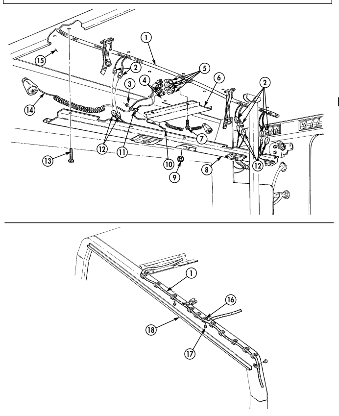
l 4-102. INTERIOR LIGHTING HARNESS ASSEMBLY REPLACEMENT (M996, M996A1) (Cont'd)
4-102. Interior Lighting Harness Assembly Replacement (M996, M996A1) (Cont'D)
-
Connect two harness leads (10) to blackout switch leads (9). 9. Install two clamps (7) and harness (2) on body (4) with two screws (8) and nuts (11).
-
Install clamp (6) and harness (2) on body (4) with screw (5). 11. Install grommet (12) on harness (2) and body (4). 12. Connect harness lead 24H (21) to lead 21G (20). 13. Install backup light cover (17) on body (16) with four lockwashers (18) and screws (19). 14. Install grommet (13) on harness (2) and body (4). 15. Install two clamps (14) and harness (2) on body (4) with two screws (15). 16. Install seven clamps (3) and harness (2) on body (4) with seven screws (1).
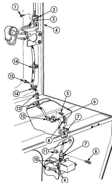
4-102. INTERIOR LIGHTING HARNESS ASSEMBLY REPLACEMENT (M996, M996A1) (Cont'd)
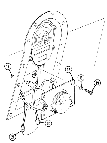
4-102. Interior Lighting Harness Assembly Replacement (M996, M996A1) (Cont'D)
- Connect two harness leads (3) on light harness leads (4). 18. Install grommet (10.1) on cover (11). 19. Position cover (11) and connect six harness leads (1) to light leads (14). 20. Install cover (11) on body (6) with ten screws (8). 21. Install clamp (9) on light harness (7) and cover (13) with screw (10) and nut (5). 22. Install cover (13) and clamp (2.1) on body (6) with four screws (12). 23. Install grommet (15) on harness (16). 24. Position grommet (19) and harness (16) in control box (25). 25. Install cover (17) on body (6) with four screws (18). 26. Connect lead 791B (29) to NBC harness lead 791A (27). 27. Install eight leads (20) on terminal block (26) and ground buss (28) with eight screws (21). 28. Install cover (22) on control box (25) with four screws (23) and lockwashers (24).
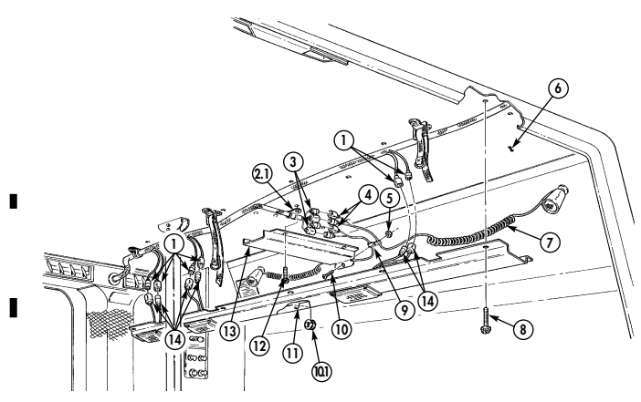
4-102. INTERIOR LIGHTING HARNESS ASSEMBLY REPLACEMENT (M996, M996A1) (Cont'd)
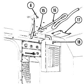
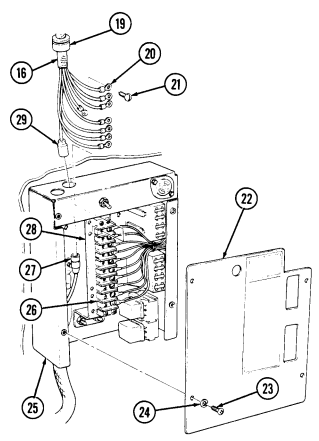
FOLLOW-ON TASKS: - Install rear close out panel (para. 11-182) · Connect battery ground cable (para. 4-73). · Check operation of interior dome lights (TM 9-2320-280-10).
- Install rear door blackout switch/bracket (para. 4-93). - Install electrical outlet/bracket (para. 4-90).
4-103. Wiring Harness Duct Assembly Replacement
This task covers: a. Spotlight Branch Duct Removal c. Main Duct Installation INITIAL SETUP: Applicable Models M996, M996A1, M997, M997A1, M997A2 Tools General mechanic's tool kit: automotive (Appendix B, Item 1) b. Main Duct Removal d. Spotlight Branch Duct Installation Manual References TM 9-2320-280-10 TM 9-2320-280-24P Equipment Condition Battery ground cable disconnected (para. 4-73).
Harness duct replacement for M996, M996A1, M997, M997A1, and M997A2 are basically the same. This procedure covers M996 and M996A1 models only.
A. Spotlight Branch Duct Removal
-
Remove four screws (12) from duct (2), clamp (3), and ceiling (4) and pull duct (2) away from ceiling (4) for access to spotlight harness clamp (5).
-
Remove screw (11), nut (6), and spotlight wiring clamp (5) from duct (2).
B. Main Duct Removal Note
-
Spotlight branch duct must be removed before removing main duct. Main duct must be installed before installing spotlight branch duct.
-
Prior to removal, tag leads for installation.
-
Remove ten screws (8) from duct (7) and ceiling (4) and pull duct (7) away for access to wiring harness leads (1).
-
Disconnect six light assembly leads (9) from wiring harness leads (1) and remove duct (7). 3. Remove two ceiling lights (10) and blackout light (13) (para. 4-87). 4. Inspect grommet (11.1) for damage. Replace if damaged.
C. Main Duct Installation
- Install two ceiling lights (10) and blackout light (13) (para. 4-87). 2. Connect six light assembly leads (9) to wiring harness leads (1). 3. Install duct (7) on ceiling (4) with ten screws (8)
D. Spotlight Branch Duct Installation
- Install spotlight harness clamp (5) on duct (2) with screw (11) and nut (6). 2. Install duct (2) and clamp (3) on ceiling (4) with four screws (12).
4-103. Wiring Harness Duct Assembly Replacement (Cont'D)
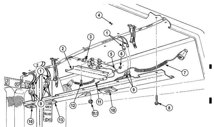
FOLLOW-ON TASKS: - Connect battery ground cable (para. 4-73).
- Check operation of interior lights (TM 9-2320-280-10).
4-104. Resuscitator/Aspirator Cable Replacement
This task covers: a. Removal b. Installation INITIAL SETUP: Applicable Models Manual References M996, M996A1, M997, M997A1, M997A2 TM 9-2320-280-24P Tools General mechanic's tool kit: automotive (Appendix B, Item 1)
Replacement of resuscitator/aspirator cable is basically the same for M996, M996A1, M997, M997A1, and M997A2 vehicles. This procedure covers M997, M997A1, and M997A2 vehicles.
For instructions on replacement of rivets, refer to para. 10-66.
a. Removal 1. Remove two screws (3), clamps (7), and cable (1) from body (2) and floor (6). 2. Remove nine rivets (4) from cable duct (5) and floor (6) and slide duct (5) left to remove. 3. Remove two screws (9), clamps (10), cable (1), and power harness clamp (8) from body (2). 4. Remove grommet (11) from floor (6) and remove cable (1) through hole in floor (6).
- Install grommet (11) in floor (6). 2. Route cable (1) through grommet (11) in floor (6) and position in approximate mounting location. 3. Connect cable (1) to resuscitator and power source. (Leave slack at each end of cable before clamping to connect resuscitation equipment if not installed.)
- Install two clamps (7) and cable (1) on body (2) and floor (6) with two screws (3). 5. Install cable duct (5) over cable (1) and slide to right under heat duct to mounting position. 6. Install cable duct (5) on floor (6) with nine rivets (4). 7. Install two clamps (10), cable (1), and power harness clamp (8) on body (2) with two screws (9).
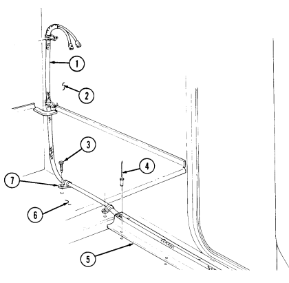
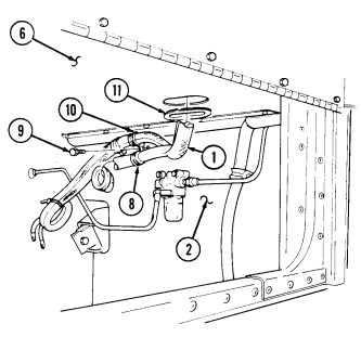
4-104. Resuscitator/Aspirator Cable Replacement (Cont'D)
4-105. Antenna Cables Replacement (M996, M996A1)
| Applicable Models |
|---|
| M996, M996A1 |
| Tools |
| General mechanic's tool kit: |
This task covers: INITIAL SETUP: automotive (Appendix B, Item 1)
Materials/Parts
Two tiedown straps (Appendix G, Item 307)
a. Removal b. Installation
Battery ground cable disconnected (para. 4-73).
| TM 9-2320-280-24P |
|---|
| Equipment Condition |
| Manual References |
|---|
| TM 9-2320-280-2 |
A. Removal
- Remove two tiedown straps (6) from antenna cables (8), power cable (2), and intercom cable (7).
Discard tiedown straps (6).
- Remove two antenna cables (8) from antenna (16).
B. Installation
-
Install antenna cables (8) on antenna (16). 2. Install clamp (9) two antenna cables (8) and intercom cable (7) on plate (15) and windshield (12) with washer (13) and capscrew (14). Tighten capscrew (14) 6 lb-ft (8 N•m).
-
Install three clamps (10), two antenna cables (8) and intercom cable (7) on windshield (12) with three screws (11).
-
Install clamp (5), two antenna cables (8) and intercom cable (7) on radio rack (1) with washer (4) and capscrew (3). (Tighten capscrew (3) 6 lb-ft (8 N•m).
-
Install two antenna cables (8) on intercom cable (7) and power cable (2) with two tiedown straps (6).
-
Remove capscrew (3), washer (4), clamp (5), two antenna cables (8), and intercom cable (7) from radio rack (1).
-
Remove three screws (11), clamps (10), two antenna cables (8) and intercom cable (7) from windshield (12).
-
Remove capscrew (14), washer (13), clamp (9), two antenna cables (8) and intercom cable (7) from plate (15) and windshield (12).
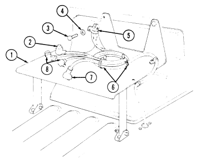
4-105. ANTENNA CABLES REPLACEMENT (M996, M996A1) (Cont'd)
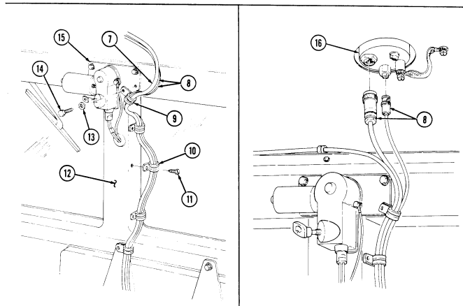
FOLLOW-ON TASK: Connect battery ground cable (para. 4-73).
4-106. Antenna Cables Replacement (M997, M997A1, M997A2)
| Applicable Models |
|---|
| M996, M996A1 |
| Tools |
| General mechanic's kit: |
| automotive (Appendix B, Item 1) |
| Materials/Parts |
This task covers:
Initial Setup:
Two tiedown straps (Appendix G, Item 308) Two lockwashers (old configuration only) (Appendix G, Item 138) Two assembled locknuts (old configuration only) (Appendix G, Item 130) Six assembled locknuts (new configuration only) (Appendix G, Item 130)
a. Removal b. Installation
A. Removal
| Equipment Condition |
|---|
| NBC control panel removed (para. 4-124). |
| Manual References | TM 9-2320-280-10 |
|---|
- Remove two tiedown straps (5) from antenna cables (7), power cable (8), and intercom cable (6).
Discard tiedown straps (5).
-
Remove capscrew (1), washer (2), clamp (3), antenna cables (7), and intercom cable (6) from radio rack (4).
-
Remove three screws (10), clamps (11), antenna cables (7), and intercom cable (6) from windshield (12).
-
Remove capscrew (13), washer (14), clamp (9), antenna cables (7), and intercom cable (6) from windshield (12) and plate (15).
4-106. ANTENNA CABLES REPLACEMENT (M997, M997A1, M997A2) (Cont'd)
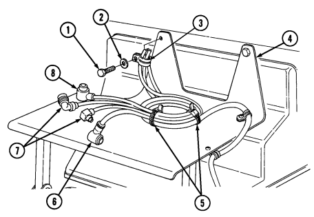
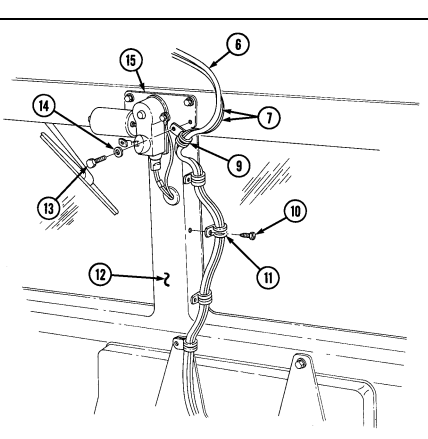
4-106. Antenna Cables Replacement (M997, M997A1, M997A2) (Cont'D)
- Remove three screws (12), clamps (11), antenna cables (4), intercom cable (16), and harness (9) from windshield (10).
•Perform steps 6 through 8 for old configuration. •Perform steps 9 through 11 for new configuration.
-
Remove assembled locknut (13), capscrew (19), washer (18), clamp (17), antenna cables (4), retainer (14), and grommet (15) from body (8). Discard assembled locknut (13).
-
Remove assembled locknut (1), screw (3), clamp (2), and antenna cables (4) from body (8). Discard assembled locknut (1).
-
Remove two antenna cables (4) from antenna (7).
-
Remove two capscrews (20), lockwashers (21), clamp (5), ground strap (6), and antenna cables (4) from antenna (7) and body (8). Discard lockwashers (21).
-
Remove two assembled locknuts (30), capscrews (23), washers (24), clamps (25), and antenna cables (4) from reinforcement (22). Discard assembled locknuts (30).
-
Remove two assembled locknuts (29), capscrews (26), washers (27), clamps (28), and antenna cables (4) from body (8). Discard assembled locknuts (29).
-
Remove two assembled locknuts (13), capscrews (19), grommet (15), retainer (14), intercom cable (16), and antenna cables (4) from body (8). Discard assembled locknuts (13).
4-106. ANTENNA CABLES REPLACEMENT (M997, M997A I, M997A2) (Cont'd)
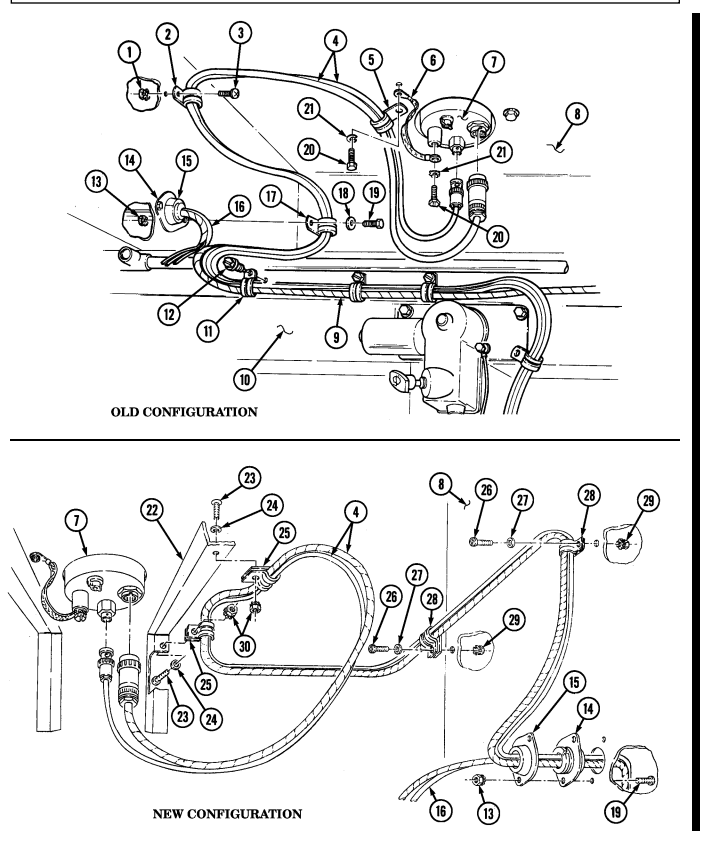
4-106. Antenna Cables Replacement (M997, M997A1, M997A2) (Cont'D)
b. Installation 1. Connect two antenna cables (4) to antenna (7).
- Perform steps 2 through 4 for old configuration. - Perform steps 5 through 7 for new configuration.
-
Install clamp (5) on antenna cables (4) and ground strap (6) on body (8) and antenna (7) with two lockwashers (21) and capscrews (20). Tighten capscrews (20) 26 lb-ft (35 N•m).
-
Install clamp (2) and two antenna cables (4) on body (8) with screw (3) and assembled locknut (1). 4. Install clamp (17) and two antenna cables (4) on grommet (15), retainer (14), and body (8) with capscrew (19), washer (18), and assembled locknut (13).
-
Install two clamps (26) on antenna cables (4) and reinforcement (23) with washers (25), capscrews (24), and assembled locknuts (31).
-
Install grommet (15) and retainer (14) on antenna cables (4), wiring harness (9), intercom cable (16), and body (8) with two capscrews (19) and assembled locknuts (13).
-
Install two clamps (29) to antenna cables (4) on body (8) with washers (28), capscrews (27), and assembled locknuts (30).
-
Install three clamps (11) to antenna cables (4) and intercom cable (16) on windshield (10) with three screws (12).
-
Install clamp (35) to antenna cables (4) and intercom cable (16) on plate (34) with washer (33) and
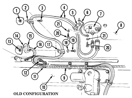
capscrew (32). Tighten capscrew (32) 72 lb-in. (8 N•m).
-
Install three clamps (37) on antenna cables (4) and intercom cable (16) on windshield (10) with three screws (36).
-
Install clamp (41) to antenna cables (4) and intercom cable (16) on radio rack (42) with washer (40) and capscrew (39). Tighten capscrew (39) 72 lb-in. (8 N•m).
-
Install two tiedown straps (43) and antenna cables (4) on intercom cable (16) and power cable (38) on radio rack (42).
4-106. Antenna Cables Replacement (M997, M997A1, M997A2) (Cont'D)
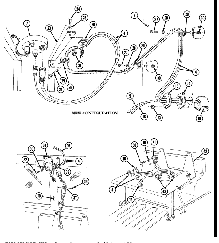
FOLLOW-ON TASKS: - Connect battery ground cable (para. 4-73).
- • - -
4-107. Intercom Cable Replacement (M996, M996A1)
This task covers:
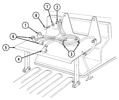
INITIAL SETUP
| Applicable Models |
|---|
General mechanic's tool kit: automotive (Appendix B, Item 1)
Materials/Parts
| Equipment Condition |
|---|
Plain-assembled nut (Appendix G, Item 201) Two assembled locknuts (Appendix G, Item 130) Two tiedown straps (Appendix G, Item 307)
a. Removal b. Installation
| Manual References |
|---|
| TM 9-2320-280-10 |
| TM 9-2320-280-24P |
Equipment Condition __________________ Battery ground cable disconnected (para. 4-73).
A. Removal
- Remove two tiedown straps (3) from intercom cable (4), power cable (7) and two antenna cables (6).
Discard tiedown straps (3).
-
Remove capscrew (8), washer (1), clamp (2), two antenna cables (6), and intercom cable (4) from radio rack (5).
-
Remove three screws (13), clamps (14), two antenna cables (6), and intercom cable (4) from windshield (15).
-
Remove capscrew (9), washer (10), clamp (12), intercom cable (4), and two antenna cables (6) from plate (11).
-
Remove two screws (22), clamps (23), and intercom cable (4) from body (17). 6. Remove two assembled locknuts (16), capscrews (21), washers (20), grommet (18), retainer (19), and intercom cable (4) from body (17). Discard assembled locknuts (16).
4-107. INTERCOM CABLE REPLACEMENT (M996, M996A1) (Cont'd)
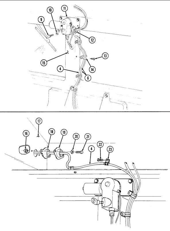
4-107. Intercom Cable Replacement (M996, M996A1) (Cont'D)
-
Loosen two clamps (12) and remove hose assemblies (11) from filter canisters (10). 8. Disconnect electrical harness lead (20) from precleaner (3). 9. Remove screw (1) and ground wire (2) from precleaner (3).
-
Disconnect latch (7) and remove precleaner (3) from bracket (4). 11. Remove four capscrews (15), washers (14), large washers (13), nuts (9) and bracket (4) from body (8).
-
Remove two nuts (16), screws (19), clamps (17), and intercom cable (18) from body (8). 13. Remove three screws (5), clamps (6), and intercom cable (18) from body (8). 14. Remove two screws (25), washers (24), retainer (27), grommet (26), intercom cable (18), and harness (21) from body (8).
-
Remove capscrew (30), plain-assembled nut (26.1), clamp (28), and intercom cable (18) from NBC heater (31). Discard plain-assembled nut (26.1).
-
Remove screw (32), clamp (33), and intercom cable (18) from body (8). 17. Disconnect intercom cable (18) from intercom (34). Remove intercom cable (18) from vehicle while ensuring proper alignment of intercom cable connector (37) to avoid damage to wiring harness (35) as intercom cable (18) passes through hole (22) in bulkhead wall (36).
B. Installation
-
Ensure proper alignment of intercom cable connector (37) to avoid damage to wiring harness (35) as intercom cable (18) passes through hole (22) in bulkhead wall (36). Route intercom cable (18) through vehicle in approximate mounting location. Ensure yellow tape (23) is located in hole (22).
-
Connect intercom cable (18) to intercom (34). 3. Install clamp (33) and intercom cable (18) on body (8) with screw (32). 4. Install clamp (28) and intercom cable (18) on NBC heater (31) with plain-assembled nut (26.1) and capscrew (30).
-
Install grommet (26), retainer (27), over yellow tape (23) intercom cable (18), and harness (21) in body (8) with two washers (24) and screws (25).
-
Install three clamps (6) and intercom cable (18) on body (8) with three screws (5). 7. Install two clamps (17) and intercom cable (18) on body (8) with two screws (19) and nuts (16). 8. Install bracket (4) on body (8) with four capscrews (15), washers (14), large washers (13), and nuts (9).
-
Install precleaner (3) on bracket (4) with latch (7).
-
Install ground wire (2) on precleaner (3) with screw (1). 11. Connect electrical harness lead (20) to precleaner (3). 12. Install two hose assemblies (11) to filter canisters (10) with two clamps (12).
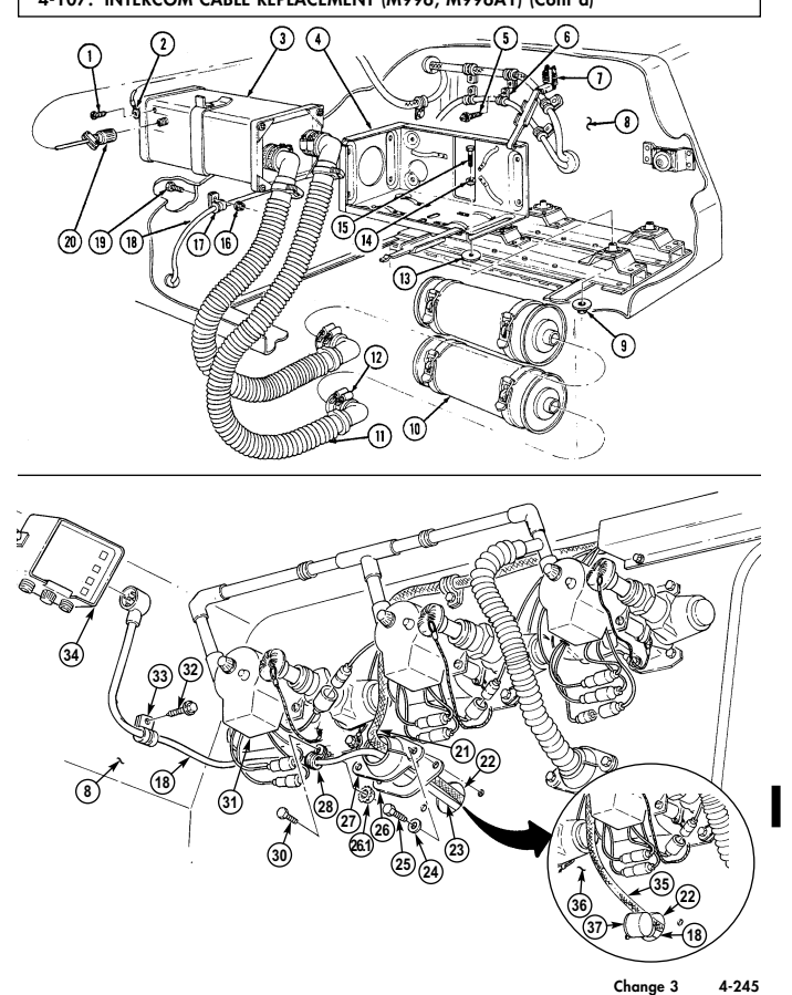
4-107. INTERCOM CABLE REPLACEMENT (M996, M996A1) (Cont'd)
4-107. Intercom Cable Replacement (M996, M996A1) (Cont'D)
-
Install grommet (3), retainer (4), and intercom cable (7) on body (2) with two washers (5), capscrews (6), and assembled locknuts (1).
-
Install two clamps (9) and intercom cable (7) on body (2) with two screws (8). 15. Install clamp (13), intercom cable (7), and two antenna cables (16) on plate (12) and windshield (17)
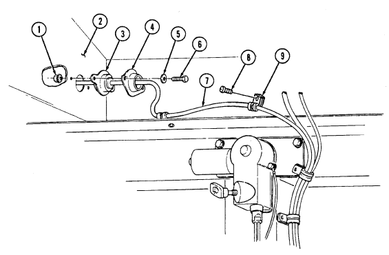
with washer (11) and capscrew (10). Tighten capscrew (10) to 6 lb-ft (8 N•m).
-
Install three clamps (15), intercom cable (7), and two antenna cables (16) on windshield (17) with three screws (14).
-
Install clamp (19), intercom cable (7), and two antenna cables (16) on radio rack (21) with washer (18) and capscrew (23). Tighten capscrew (23) to 6 lb-ft (8 N•m).
-
Install intercom cable (7) on antenna cables (16) and power cable (22) with two tiedown straps (20).
4-107. INTERCOM CABLE REPLACEMENT (M996, M996A1) (Cont'd)
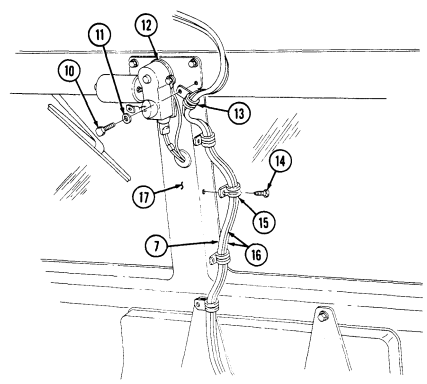
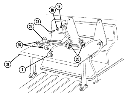
FOLLOW-ON TASKS: - Connect battery ground cable (para. 4-73).
- Test NBC system operation (TM 9-2320-280-10)
4-108. Intercom Cable Replacement (M997, M997A1, M997A2)
This task covers:
| Materials/Parts |
|---|
INITIAL SETUP:
| Applicable Models |
|---|
| M996, M996A1 |
| Tools |
| General mechanic's kit: |
automotive (Appendix B, Item 1) Two tiedown straps (Appendix G, Item 308) Seven assembled locknuts (Appendix G, Item 130) a. Removal
a. Removal b. Installation
| Manual References |
|---|
| TM 9-2320-280-10 |
| TM 9-2320-280-24P |
TM 9-2320-280-10 Equipment Condition
- Battery ground cable disconnected (para. 4-73). - NBC door opened (TM 9-2320-280-10).
Removal and installation of intercom cable is basically the same for old and new antenna mount configurations. This procedure covers the old configuration.
- Remove two tiedown straps (3) from intercom cable (4), power cable (7), and two antenna cables (6).
Discard tiedown straps (3).
-
Remove capscrew (8), washer (1), clamp (2), antenna cables (6), intercom cable (4), and power cable (7) from radio rack (5).
-
Remove three screws (13), clamps (14), two antenna cables (6), and intercom cable (4) from windshield (15).
-
Remove capscrew (9), washer (10), clamp (12), intercom cable (4), and two antenna cables (6) from plate (11) and windshield (15).
-
Remove three screws (25), clamps (24), intercom cable (4), two antenna cables (6), and wiring harness (23) from body (19).
-
Remove two assembled locknuts (16), capscrews (21), washers (20), grommet (17), retainer (18), intercom cable (4), wiring harness (23), two antenna cables (6), and clamp (22) from body (19). Discard assembled locknuts (16).
4-108. INTERCOM CABLE REPLACEMENT (M997, M997A1, M997A2) (Cont'd)
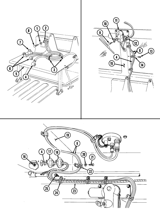
4-108. Intercom Cable Replacement (M997, M997A1, M997A2) (Cont'D)
-
Remove three assembled locknuts (3), capscrews (7), and cover (2) from body (6). Discard assembled locknuts (3).
-
Remove two screws (4), clamps (5), intercom cable (1), and wiring harness (8) from body (6). 9. Remove two assembled locknuts (5.3), capscrews (5.2), and clamps (5.1) from body (6). Discard assembled locknuts (5.3).
-
Remove two screws (13), washers (12), grommet (10), retainer (11), intercom cable (1), and wiring harness (8) from body (6).
-
Remove intercom cable (1) from intercom (14) and vehicle.
b. Installation 1. Install intercom cable (1) on intercom (14). 2. Route intercom cable (1) in vehicle in approximate mounting location. 3. Install grommet (10), retainer (11), and wiring harness (8) over yellow tape (9), and intercom cable (1) on body (6) with two washers (12) and screws (13).
-
Install two clamps (5.1), intercom cable (1), and wiring harness (8) on body (6) with two capscrews (5.2) and assembled locknuts (5.3).
-
Install two clamps (5), intercom cable (1), and wiring harness (8) on body (6) with two screws (4).
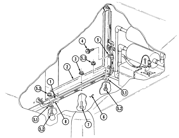 6. Install cover (2), intercom cable (1), and wiring harness (8) on body (6) with three capscrews (7) and assembled locknuts (3).
4-108. Intercom Cable Replacement (M997, M997A1, M997A2) Cont'D)
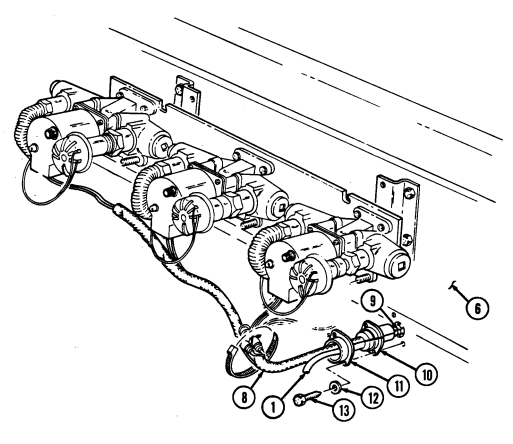
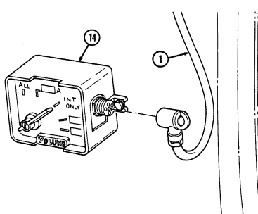
4-108. Intercom Cable Replacement (M997, M997A1, M997A2) (Cont'D)
-
Install grommet (3), retainer (4), intercom cable (2), wiring harness (10), and two cables (6) on body (5) with two capscrews (8), washers (7), clamp (9), and two assembled locknuts (1).
-
Install three clamps (12), intercom cable (2), antenna cables (6), and wiring harness (10) on body (5) with three screws (13).
-
Install clamp (17), intercom cable (2), and antenna cables (6) on plate (16) and windshield (11) with washer (15) and screw (14). Tighten screw (14) to 71 lb-in. (8 N•m).
-
Install three clamps (19), intercom cable (2), and antenna cables (6) on windshield (11) with three screws (18).
-
Install clamp (21), intercom cable (2), and antenna cables (6) on radio rack (23) with washer (20) and capscrew (25). Tighten capscrew (25) to 71 lb-in. (8 N•m).
-
Secure intercom cable (2), antenna cables (6), and power cable (24) together with two tiedown
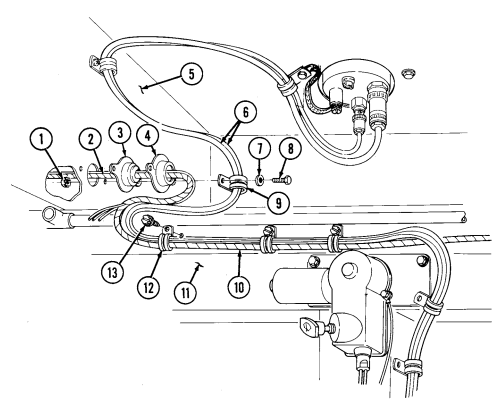
straps (22) on radio rack (23).
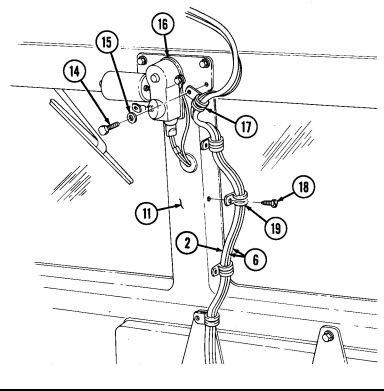
4-108. INTERCOM CABLE REPLACEMENT (M997, M997A1, M997A2) (Cont'd)
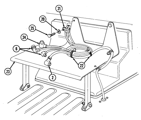
FOLLOW-ON TASKS: - Connect battery ground cable (para. 4-73).
•Close NBC door (TM 9-2320-280-10).
4-109. 200 Ampere Alternator (Aa0013036Aa) Replacement
This task covers: a. Removal b. Installation
| INITIAL SETUP: | |
|---|---|
| Applicable Models | Manual References |
| M996, M996A1 | TM 9-2320-280-24P |
| Tools | Equipment Condition |
| General mechanic's tool kit: | Battery ground cable disconnected (para. 4-73). |
| automotive (Appendix B, Item 1) | |
| Materials/Parts | |
| Two tiedown straps (Appendix G, Item 307) | |
| a. Removal | |
| 1. | Remove two tiedown straps (6) from antenna cables (8), power cable (2), and intercom cable (7). |
| Discard tiedown straps (6). |
A. Removal
- Remove four screws (1), lockwashers (21), cover (2), and gasket (3) from regulator (4). Discard lockwashers (21).
Prior to removal, tag leads for installation.
-
Remove nut (13), lockwasher (12), washer (11.1), and lead 2A (11) from stud (10). Discard lockwasher (12).
-
Remove nut (15), washer (16), nut (14.1), and lead 5A (14) from stud (5). 4. Remove rubber wedge (17) from opening in regulator (4). 5. Disconnect lead 568A (19) from harness lead (20). 6. Remove tiedown strap (18) securing lead 568A (19) to leads 5A (14) and 2A (11). Discard tiedown strap (18).
Perform steps 8 and 9 for vehicles with revised new configuration.
-
Loosen two capscrews (9) on alternator adjusting bracket (6) and two capscrews (38) on alternator mounting bracket (40) and support bracket (39).
-
Loosen capscrew (9), lockwasher (36), and washer (37) on alternator adjusting bracket (6). 9. Loosen nut (41) on alternator mounting bracket (40).
-
Remove three drivebelts (7) from alternator pulley (8). 11. Slide back rubber boot (27) and remove nut (23), lockwasher (24), washer (25), fuse (26), insulator washer (22), alternator positive cable (28), and bushing (29) from positive stud (30). Discard lockwasher (24).
-
Remove nut (35), lockwasher (34), lead 3B (31), and ground strap (33) from ground stud (32).
Discard lockwasher (34).
4-109. 200 AMPERE ALTERNATOR (AA0013036AA) REPLACEMENT (Cont'd)
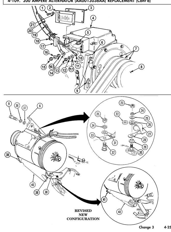
l
4-109. 200 Ampere Alternator (Aa0013036Aa) Replacement (Cont'D)
.Warning.
Alternator must be supported during removal and installation. Failure to support alternator may cause injury to personnel or damage to equipment.
- Remove capscrew (1), lockwasher (2), and washer (3) from alternator (13) and adjusting bracket (4). Discard lockwasher (2).
Note
-
Perform step 15 for vehicles with new alternator support bracket c o n f i g u r a t i o n .
-
Perform step 16 for vehicles with revised new configuration.
-
Remove two capscrews (16), lockwashers (15), and washers (14) from alternator (13), support bracket (11), and mounting bracket (12). Discard lockwashers (15).
-
Remove two capscrews (16), lockwashers (15), washers (14), and spacer (27) from alternator (13), power steering lines bracket (21), support bracket (23), and mounting bracket (12). Discard lockwashers (15).
-
Remove nut (26), lockwasher (18), washer (19), long capscrew (22), and washer (20) from alternator (13), power steering lines bracket (21), support bracket (23), and mounting bracket (25). Discard lockwasher (18).
-
Remove alternator (13). 18. Remove five screws (5), washers (6), and guard (7) from alternator (13). 19. Remove alternator pulley (17) (para. 4-3).
B. Installation
- Install alternator pulley (17) (para. 4-3). 2. Install guard (7) to alternator (13) with five washers (6) and screws (5).
Note
- Perform step 4 for vehicles with new alternator support bracket c o n f i g u r a t i o n .
-
Position alternator (13) on mounting bracket (25) with support bracket (23) and power steering lines bracket (21) on the outside of alternator mounting flange (24) and install washer (20), long capscrew (22), washer (19), lockwasher (18), and nut (26).
-
Align alternator (13) with adjusting bracket (4) and install washer (3), lockwasher (2), and capscrew (1). Do not tighten capscrew (1).
- Perform step 5 for vehicles with revised new configuration.
-
Position alternator (13) on mounting bracket (12) with support bracket (11) between mounting bracket (12) and alternator (13) and install two washers (14), lockwashers (15), and capscrews (16). Do not tighten capscrews (16).
-
Position alternator (13) on mounting bracket (12) with support bracket (23) and power steering lines bracket (21) on the outside of alternator mounting flange (24) and install spacer (27), two washers (14), lockwashers (15), and capscrews (16).
4-109. 200 Ampere Alternator (Aa0013036Aa) Replacement (Cont'D)
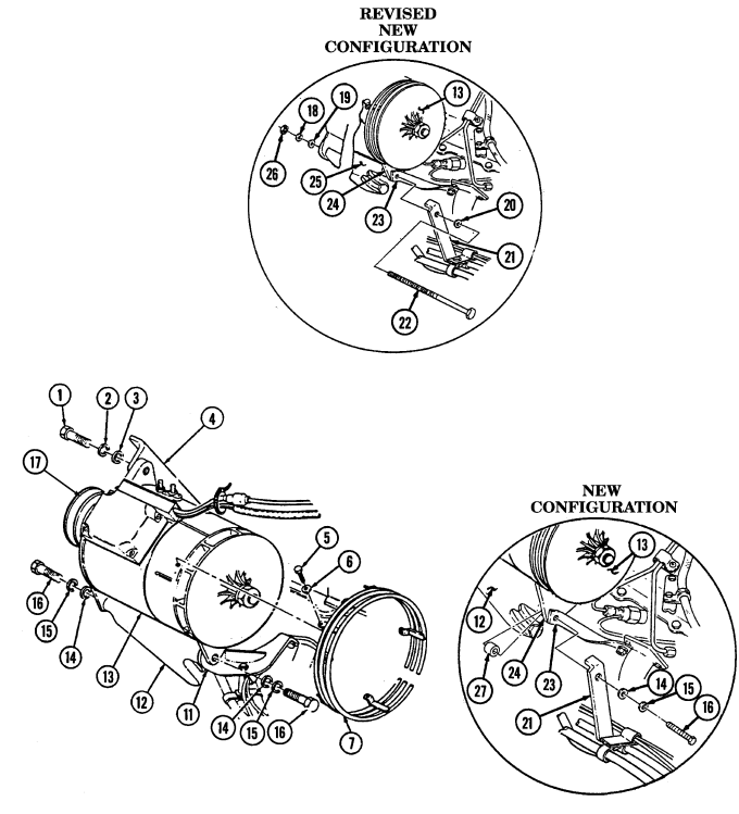
4-109. 200 Ampere Alternator (Aa0013036Aa) Replacement (Cont'D)
Ensure terminals are clean before connections are made.
- Install ground strap (25) and lead 3B (23) to ground stud (24) with lockwasher (26) and nut (22).
Tighten nut (22) to 96-144 lb-in. (11-16 N•m).
- Install insulator (27) in fuse (31). 9. Install bushing (34), positive cable (33), fuse (31), and insulator (27) on positive stud (35) with washer (30), lockwasher (29), and nut (28). Tighten nut (28) to 10-15 lb-ft (14-20 N•m). Slide rubber boot (32) over nut (28).
Perform step 10 for vehicles equipped with deep water fording kits.
-
Apply sealant to positive stud (35) and positive cable (33) so that all exposed metallic surfaces are coated. The sealant should be evenly applied with a minimum thickness of 0.06 in. (1.5 mm).
-
Tighten two capscrews (9) on alternator mounting bracket (6) to 40 lb-ft. (54 N•m). 12. Install three drivebelts (7) on alternator pulley (8). 13. Install lead 5A (14) to stud (5) with washer (16), nut (14.1), and nut (15). 14. Install lead 2A (11) to stud (10) with washer (11.1), lockwasher (12), and nut (13). 15. Install rubber wedge (17) in opening in regulator (4). 16. Install gasket (3) and cover (2) to regulator (4) with four lockwashers (21) and screws (1). 15. Connect lead 568A (19) to harness lead (20) and secure to leads 2A (11) and 5A (14) using tiedown straps (18).
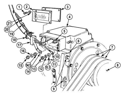
4-109. 200 Ampere Alternator (Aa0013036Aa) Replacement (Cont'D)
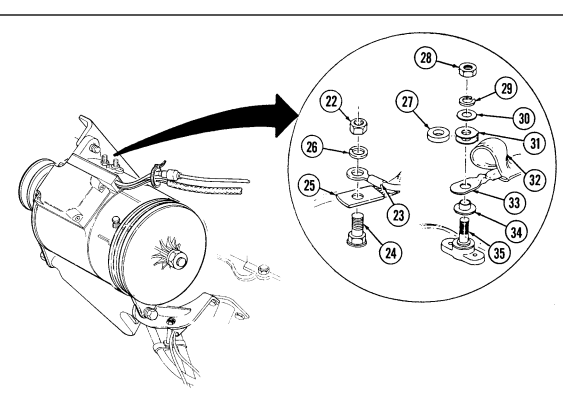
FOLLOW-ON TASKS: - Adjust alternator belts (para. 3-82).
· Connect battery ground cable (para. 4-75). - Lower and secure hood (TM 9-2320-280-10).
4-110. 200 Ampere Alternator (12338796-1) Replacement (6.2L)
This task covers:
a. Removal b. Installation
INITIAL SETUP:
| Applicable Models _______________ | Manual References ________________ |
|---|---|
| M997, M997A1, M997A2 | TM 9-2320-280-10 |
| TM 9-2320-280-24P | |
| Tools | |
| General mechanic's tool kit: | Equipment Condition __________________ |
| automotive (Appendix B, Item 1) | - NBC door opened (TM 9-2320-280-10). |
| - Battery ground cable disconnected (para. 4-73). | |
| Materials/Parts _____________ | |
| Two tiedown straps (Appendix G, Item 308) | |
| Two lockwashers (old configuration only) | |
| (Appendix G, Item 138) | |
| Two assembled locknuts (old configuration only) |
a. Removal NOTE Prior to removal, tag leads for installation.
-
Remove nut (25), lockwasher (24), washer (23), lead 3B (22), and ground strap (21) from ground stud (20). Discard lockwasher (24).
-
Slide back rubber boot (26) and remove nut (1), lockwasher (2), washer (3), fuse link (4), insulator washer (27), alternator positive cable (5), and washer (6) from positive stud (7). Discard lockwasher (2).
-
Loosen two capscrews (12) and (14) on alternator adjusting bracket (9) and two capscrews (15) securing alternator (18) to alternator mounting bracket (17) and support bracket (16).
-
Remove three drivebelts (8) from alternator pulley (19).
.Warning.
Alternator must be supported during removal and installation. Failure to support alternator may cause injury to personnel or damage to equipment.
-
Remove capscrew (12), lockwasher (11), and washer (10) securing alternator (18) to adjusting bracket (9). Discard lockwasher (11).
-
Remove capscrew (14), washer (13), and alternator adjusting bracket (9) from mounting bracket (17).
4-110. 200 AMPERE ALTERNATOR (12338796-1) REPLACEMENT (6.2L) (Cont'd)
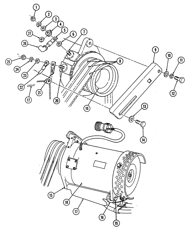
4 - 1 1 0 . 200 Ampere Alt E R N Ator (12338796-1) Replacement (6.2L) (Cont'D)
- Remove two capscrews (18), lockwashers (19), and washers (20) securing alternator (24) to support bracket (21) and mounting bracket (23). Discard lockwashers (19).
Note
-
Perform step 8 for vehicles with new alternator support bracket configuration.
-
Perform step 9 for vehicles with revised new configuration.
-
Remove two capscrews (18), lockwashers (19), washers (20), and spacer (27) securing alternator (24), power steering lines bracket (25), and support bracket (21) to mounting bracket (23). Discard lockwashers (19).
-
Remove nut (37), lockwasher (19), washer (20), long capscrew (38), and washer (20) securing alternator (24), power steering lines bracket (25), and support bracket (21) to mounting bracket (23), and alternator flange (26). Discard lockwasher (19).
-
Remove alternator (24).
-
Remove three capscrews (15), washers (16), and bushings (22) securing fan guard assembly (17) to alternator (24).
-
Remove alternator pulley (28) (para. 4-3).
B Installation
-
Install alternator pulley (28) (para. 4-3). 2. Install fan guard assembly (17) on alternator (24) and secure with three bushings (22), washers (16), and capscrews (15).
-
Position alternator (24) on mounting bracket (23) with support bracket (21) between mounting bracket (23) and alternator (24) and install two washers (20), lockwashers (19), and capscrews (18). Do not tighten capscrews (18).
Note
- Perform step 4 for vehicles with new alternator support bracket configuration.
- Position alternator adjusting bracket (9) and install washer (10), lockwasher (11), and capscrew (12). Do not tighten capscrew (12).
Note
Ensure terminals are clean before connections are made.
-
Align alternator (24) with adjusting bracket (9) and install washer (13) and capscrew (14). Do not tighten capscrew (14).
-
Install insulator washer (36) in fuse link (4). 9. Install washer (6), positive cable (5), fuse link (4), and insulator washer (36) on postive stud (7) and secure with washer (3), lockwasher (2), and nut (1). Tighten nut (1) to 10-15 lb-ft (14-20 N•m).
-
Install ground strap (30) and lead 3B (31) to ground stud (29) and secure with washer (32), lockwasher (33), and nut (34). Tighten nut (34) to 96-144 lb-in. (11-16 N•m).
-
Install rubber boot (35) over stud (7).
-
Install three drivebelts (8) on alternator pulley (28).
- Perform step 5 for vehicles with revised new configuration.
-
Position alternator (24) on mounting bracket (23) with support bracket (21) and power steering lines bracket (25) on the outside of alternator mounting flange (26) and install spacer (27), two washers (20), lockwashers (19), and capscrews (18).
-
Position alternator (24) on mounting bracket (23) with support bracket (21) and power steering lines bracket (25) on the outside of alternator mounting flange (26) and install washer (20), long capscrew (38), washer (20), lockwasher (19), and nut (37).
4-110. 200 Ampere Alternator (12338796-1) Replacement (6.2L) (Cont'D)
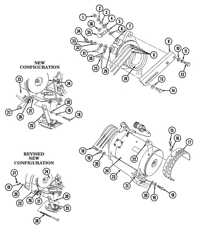
FOLLOW-ON TASKS: - Install 200 amp regulator (para. 4-115).
· Adjust alternator belt (para. 3-82).
· Connect battery ground cable (para. 4-73).
· Lower and secure hood (TM 9-2320-280-10).
4-110.1. 200 Ampere Alternator (12447109) Replacement (6.5L)
This task covers:
a. Removal b. Installation
| INITIAL SETUP | |
|---|---|
| Applicable Models | Personnel Required |
| M996, M996A1 | One mechanic |
| One assistant | |
| Tools | |
| General mechanic's tool kit: | Manual References ________________ |
| automotive (Appendix B, Item 1) | TM 9-2320-280-24P |
| Materials/Parts | Equipment Condition __________________ |
| Plain-assembled nut (Appendix G, Item 201) | Battery ground cable disconnected (para. 4-73). |
| Two assembled locknuts | |
| (Appendix G, Item 130) | |
| Two tiedown straps (Appendix G, Item 307) | |
| a. Removal |
a. Removal
Prior to removal, tag leads for installation.
-
Remove nut (14), lockwasher (13), washer (12), and ground strap (11) from ground stud (10). Discard lockwasher (13).
-
Slide back rubber boot (15) and remove nut (1), lockwasher (2), washer (3), alternator positive cable (4), nut (5), and washer (6) from positive stud (7). Discard lockwasher (2).
-
Position 3/8-in. breaker bar on belt tensioner (16), move tensioner (16) clockwise, and remove drivebelt (8) from alternator pulley (9).
Alternator must be supported during removal and installation. Failure to support alternator may cause injury to personnel or damage to equipment.
- Remove capscrew (17), lockwasher (18), and washer (19) from bracket (20) and alternator (28).
Discard lockwasher (18).
-
Remove nut (31), lockwasher (30), washer (25), screw (24), washer (25), and alternator (28) from support bracket (26) and mounting bracket (29). Discard lockwasher (30).
-
Remove three capscrews (21), washers (22), bushings (27), and fan guard assembly (23) from alternator (28).
-
Remove alternator pulley (9) (para. 4-3).
4-110.1. 200 AMPERE ALTERNATOR (12447109) REPLACEMENT (6.5L) (Cont'd)
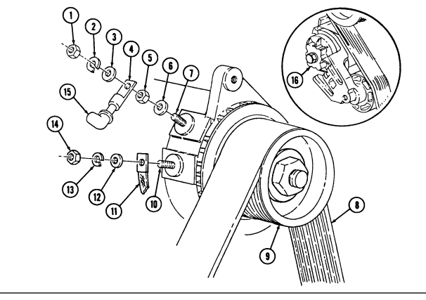
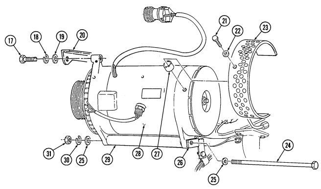
4-110.1. 200 Ampere Alternator (12447109) Replacement (6.5L) (Cont'D)
b. Installation 1. Install alternator pulley (24) (para. 4-3). 2. Install fan guard assembly (7) on alternator (12) with three bushings (11), washers (6), and capscrews (5).
Alternator must be supported during removal and installation. Failure to support alternator may cause injury to personnel or damage to equipment.
-
Position alternator (12) on mounting bracket (13) with support bracket (10) on outside of alternator (12) and install washer (9), capscrew (8), washer (9), lockwasher (14), and nut (15).
-
Install washer (3), lockwasher (2), and capscrew (1) on bracket (4) and alternator (12).
Ensure terminals are clean before connections are made.
-
Install washer (21), nut (20), and positive cable (19) on positive stud (22) with washer (18), lockwasher (17), and nut (16). Tighten nut (16) to 10-15 lb-ft (14-20 N•m).
-
Slide rubber boot (30) over stud (22). 7. Install ground strap (26) on ground stud (25) with washer (27), lockwasher (28), and nut (29).
Tighten nut (29) to 8-12 lb-ft (11-16 N•m).
- Position 3/8-in. breaker bar on belt tensioner (31), move tensioner (31) clockwise, and install belt (23) on alternator pulley (24).
4-110.1. 200 Ampere Alternator (12447109) Replacement (6.5L) (Cont'D)
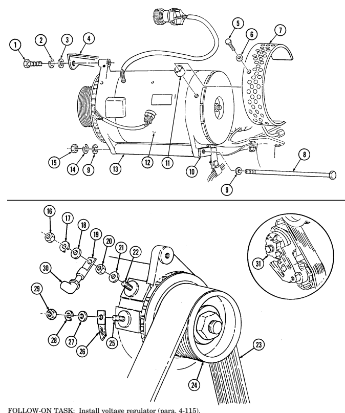
4-111. 200 Ampere Alternator Cable (12446825) Replacement
This task covers: INITIAL SETUP: Applicable Models M997A2, M1097A2, M1123 Tools General mechanic's tool kit: automotive (Appendix B, Item 1) Materials/Parts Lockwasher (Appendix G, Item 186) Lockwasher (Appendix G, Item 150) Adhesive sealant (Appendix C, Item 9)
a. Removal b. Installation
Manual References TM 9-2320-280-10 TM 9-2320-280-24P
Equipment Condition
- Battery ground cables disconnected (para. 4-73). - Hood raised and secured (TM 9-2320-280-10). - Engine access cover removed (para. 10-15).
Prior to removal, tag leads for installation.
a. Removal 1. Slide back rubber boot (1) and remove nut (3), lockwasher (4), washer (5), fuse (2), insulator (6), cable (7), and bushing (8) from positive stud (9). Discard lockwasher (4).
- Remove capscrew (11), clamp (12), and cable (7) from bracket (10). 3. Remove nut (17), lockwasher (16), washer (15), and cable (7) from buss bar (14) and remove cable (7) from battery box (13). Discard lockwasher (16).
B. Installation Note
Ensure terminals are clean before connections are made.
-
Route cable (7) through grommet (18) in battery box (13), and install cable (7) on buss bar (14) with washer (15), lockwasher (16), and nut (17).
-
Route cable (7) in approximate mounting location over heat shield, and secure cable (7) and clamp (12) on bracket (10) with capscrew (11).
-
Apply sealant to positive stud (9) and cable (7) so all exposed metallic surfaces are coated. 4. Install bushing (8), cable (7), fuse (2), and insulator (6) on positive stud (9) with washer (5), lockwasher (4), and nut (3). Tighten nut (3) to 10-15 lb-ft (14-20 N•m). Slide rubber boot (1) over nut (3).
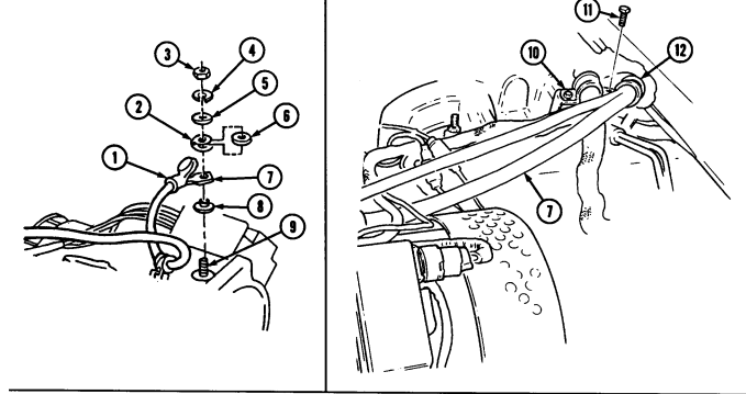
4-111. 200 Ampere Alternator Cable (12446825) Replacement (Cont'D)
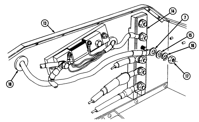
FOLLOW-ON TASKS: - Install engine access cover (para. 10-15).
- Lower and secure hood (TM 9-2320-280-10).
· Connect battery ground cables (para. 4-73).
- Start engine and check operation of voltmeter gauge (TM 9-2320-280-10).
4-112. 200 Ampere Alternator Cable (12339317) Replacement
This task covers: INITIAL SETUP: Applicable Models Tools General mechanic's tool kit: automotive (Appendix B, Item 1)
| Materials/Parts |
|---|
Two lockwashers (Appendix G, Item 191) Assembled locknut (Appendix G, Item 131) Lockwasher (Appendix G, Item 186)
a. Removal b. Installation
Materials/Parts (Cont'D)
Tiedown strap (Appendix G, Item 308) Adhesive sealant (Appendix C, Item 9) Manual References TM 9-2320-280-10 TM 9-2320-280-24P Equipment Condition
- Battery ground cable disconnected (para. 4-73). - Hood raised and secured (TM 9-2320-280-10).
Prior to removal, tag leads for installation.
a. Removal 1. Remove tiedown strap (30), screw (31), clip (32), and 200 ampere cable (8) from starter (33).
Discard tiedown strap (30).
Step 2 applies to M997 and M997A1 vehicles only. Step 3 applies to M996, M996A1, M1097, and M1097A1 vehicles only.
-
Remove assembled locknut (9), bolt (24), cable (8), and clamps (28), (25), and (27) from oil pan bracket (26). Discard assembled locknut (9).
-
Remove assembled locknut (9), bolt (24), cable (8), and clamp (28) from oil pan bracket (26). Discard assembled locknut (29).
-
Remove nut (19), washer (20), clamps (21), and (22), and cable (8) from compressor (18). 5. Remove nut (15), lockwasher (16), cable (8), and clamp (17) from engine lift bracket (1). Discard lockwasher (16).
-
Remove nut (11), lockwasher (12), cable (8), and clamp (13) from water crossover stud (14). Discard lockwasher (12).
-
Slide back rubber boot (2) and remove nut (4), lockwasher (5), washer (6), fuse (3), insulator (7), cable (8), and bushing (9) from positive stud (10). Discard lockwasher (5).
-
Remove cable (8) from vehicle.
b. Installation
Ensure terminals are clean before connections are made.
- Install bushing (9), cable (8), fuse (3), and insulator (7) on positive stud (10) with washer (6), lockwasher (5), and nut (4). Tighten nut (4) to 10-15 lb-ft (14-20 N•m). Slide rubber boot (2) over nut (4).
NOTE For vehicles equipped with deep water fording kits, perform step 2.
-
Apply sealant to positive stud (10) and cable (8) so all exposed metallic surfaces are coated. The sealant should be evenly applied with a minimum thickness of .06 in. (1.5 mm).
-
Install clamp (13) and cable (8) on water crossover stud (14) with lockwasher (12) and nut (11). 4. Install clamp (17) on cable (8) and engine lift bracket (1) with lockwasher (16) and nut (15).
M996, M996A1, M997, M997A1, M1097, M1097A1
4-112. 200 Ampere Alternator Cable (12339317) Replacement (Cont'D)
- Install clamp (22) on cable (8) and secure clamp (21) to compressor (18) with washer (20) and nut (19).
NOTE Step 6 applies to M997 and M997A1 vehicles only. Step 7 applies to M996 and M996A1 vehicles only.
-
Install clamps (28), (27), and (25) on cable (8) and oil pan bracket (26) with bolt (24) and assembled locknut (29).
-
Install clamp (28) on cable (8) and oil pan bracket (26) with bolt (24) and assembled locknut (29). 8. Install cable (8) on starter (33) with clip (32) and screw (31). Connect tiedown strap (30). 9. Apply sealant to screw (31) and cable (8) so that all exposed metallic surfaces are coated. The
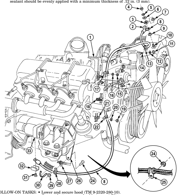
- Connect battery ground cable (para. 4-73). - Start engine and check operation of voltmeter gauge (TM 9-2320-280-10)
4-113. 200 Ampere Umbilical Power Cable Replacement
This task covers: INITIAL SETUP: Applicable Models M1097, M1097A1, M1097A2 Tools General mechanic's tool kit: automotive (Appendix B, Item 1) Materials/Parts Three lockwashers (Appendix G, Item 138) Lockwasher (Appendix G, Item 141) Lockwasher (Appendix G, Item 150) Lockwasher (Appendix G, Item 148) Silicone compound (Appendix C, Item 48) a. Removal
A. Removal B. Installation
Personnel Required One mechanic One assistant Manual References TM 9-2320-280-24P Equipment Condition
-
Batteries removed (para, 4-79). - Fixed rear door removed (para. 10-14).
-
Prior to removal, tag leads for installation. - Perform step 1 for M1097A2 vehicles only. Perform step 2 for M1097 and M1097A1 vehicles.
-
Remove nut (5) lockwasher (6), and positive power cable (7) from power stud (8). Discard lockwasher (6).
-
Remove capscrew (1), lockwasher (2), negative power cable (3), and two cables (4) from shunt (9).
Discard lockwasher (2).
Perform step 4 for M1097A2 vehicles only. Perform steps 5 and 6 for M1097 and M1097A1 vehicles only.
- Remove five capscrews (35), two washers, (34), and coverplate (33) from "B" beam (13). 5. Remove three capscrews (32) from coverplate (20) and "B" beam (13). 6. Remove three nuts (18), lockwashers (17), capscrews (21), and coverplate (20) from cargo floor (19).
Discard lockwashers (17).
-
Remove two nuts (16), washers (15), capscrews (27), washers (28), and mounting bracket (25) from coverplate (20).
-
Remove nut (29) and screw (24) from cover chain (22) and mounting bracket (25). 9. Remove cover (23) and cover chain (22) from umbilical power cable assembly (30).
-
Remove four nuts (31), screws (26), and mounting bracket (25) from umbilical power cable assembly (30).
-
Pull umbilical power cable assembly (30) through grommet (12) and coverplate (20) and remove from vehicle.
-
Remove grommet (12) from battery box (14).
-
Remove nut (5), lockwasher (6), washer (11), and positive power cable (7) from buss bar (10).
Discard lockwasher (6).
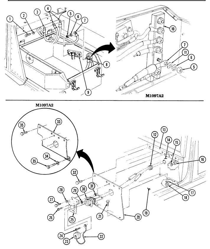
4-113. 200 AMPERE UMBILICAL POWER CABLE REPLACEMENT (Cont'd)
4-113. 200 Ampere Umbilical Power Cable Replacement (Cont'D)
B. Installation
Install grommet (12) on battery box (14). Route umbilical power cable assembly (30) through coverplate (20) and grommet (12) and position in approximate mounting location.
Install umbilical power cable assembly (30) on mounting bracket (25) with three screws (24) and nuts (31).
Install cover (23) on umbilical power cable assembly (30). Install cover chain (22) on mounting bracket (25) with screw (24) and nut (29).
Note
Perform step 6 for M1097A2 vehicles only. Perform steps 7 and 8 for M1097 and M1097A1 vehicles.
Install coverplate (33) on "B" beam (13) with two washers (34) and five capscrews (35).
Install mounting bracket (25) on coverplate (20) with two washers (28), capscrews (27), washers (15), and nuts (16).
Install coverplate (20) on "B" beam (13) with three capscrews (32).
Install coverplate (20) to cargo floor (19) with three capscrews (21), lockwashers (17), and nuts (18).
Tighten nuts (18) to 65 lb-ft (88 N*m).
Install two cables (4) and negative power cable (3) on shunt (9) with lockwasher (2) and capscrew (1).
Note Perform step 11 for M1097A2 vehicles only. Perform step 12 for M1097 and M1097A1 vehicles.
Install positive power cable (7) on buss bar (10) with washer (11), lockwasher (6), and nut (5).
Install positive power cable (7) on power stud (8) with lockwasher (6) and nut (5). Apply silicone compound to cable (7) so that all exposed metallic surfaces are coated.
4-113. 200 Ampere Umbilical Power Cable Replacement (Cont'D)
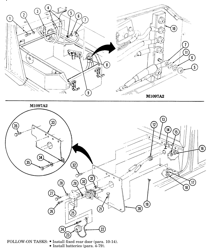
| Materials/Parts |
|---|
| Applicable Models |
|---|
| M997A2, M1025A2, M1035A2, M1043A2, |
| M1045A2, M1097A2, M1123 |
| Tools |
| General mechanic's tool kit: |
4-114. 200 Ampere Regulator (A0013036Aa) Replacement
| INITIAL SETUP: |
|---|
| This task covers: |
|---|
Four lockwashers (Appendix G, Item 138) Six lockwashers (Appendix G, Item 142) Four lockwashers (Appendix G, Item 143)
a. Removal b. Installation
| Personnel Required |
|---|
| One mechanic |
| One assistant |
| Manual References |
| TM 9-2320-280-24P |
A. Removal
- Remove four screws (1), lockwashers (2), cover (3), and gasket (4) from regulator (5). Discard lockwashers (2).
Prior to removal, tag leads for installation.
-
Remove nut (13), lockwasher (12), washer (11.1), and lead 2A (11) from stud (9). Discard lockwasher (12).
-
Remove nut (15), washer (16), and lead 5A (14) from stud (10). 4. Remove rubber wedge (17) from opening in regulator (5). 5. Remove four screws (6) and lockwashers (7) from regulator (5) and alternator (8) and pull regulator (5) away for access to leads (21). Discard lockwashers (7).
-
Remove five screws (23), lockwashers (22), leads (21), and regulator (5) from alternator (8). Discard lockwashers (22).
-
Remove nut (19) and lead 568A (20) from stud (10).
B. Installation
- Install lead 568A (20) on stud (10) with nut (19). 2. Install five leads (21) on regulator (5) with five lockwashers (22) and screws (23). 3. Install regulator (5) on alternator (8) with four lockwashers (7) and screws (6). 4. Install lead 5A (14) on stud (10) with washer (16) and nut (15). 5. Install lead 2A (11) on stud (9) with washer (11.1), lockwasher (12), and nut (13). 6. Install rubber wedge (17) in opening in regulator (5). 7. Install gasket (4) and cover (3) on regulator (5) with four lockwashers (2) and screws (1).
4-114. 200 AMPERE REGULATOR (A0013036AA) REPLACEMENT (Cont'd)
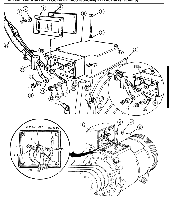
FOLLOW-ON TASKS: - Lower and secure hood (TM 9-2320-280-10).
· Connect battery ground cable (para. 4-73).
4-115. 200 Ampere Regulator (12338796-1, S-311) Replacement
This task covers: INITIAL SETUP: Applicable Models M997A2, M1025A2, M11035A2, M1043A2, M1045A2, M1097, M1097A1, M1097A2 Tools General mechanic's tool kit: automotive (Appendix B, Item 1)
Materials/Parts
Two spring tension washers (Appendix G, Item 318) Lockwasher (Appendix G, Item 185) Sealing Compound (Appendix C, Item 45)
a. Removal b. Installation
Manual References TM 9-2320-280-10 TM 9-2320-280-24P
Equipment Condition
- Battery ground cables disconnected (para. 4-73). - Hood raised and secured (TM 9-2320-280-10).
a. Removal NOTE Prior to removal, tag leads for installation.
-
Disconnect regulator plug (13) from voltage regulator (12). 2. Slide back rubber boot (4) and remove nut (3), lead 5A (2), and washer (1) from red (energize) terminal (26).
-
Slide back rubber boot (5) and remove nut (6), lead 2A (7), and washer (8) from yellow (AC) terminal (9).
Perform steps 4 and 5 for M997A2, M1025A2, M1035A2, M1043A2, M1045A2, and M1097A2 vehicles only.
-
Slide back rubber boot (22) and remove nut (23), lead (21), and washer (24) from terminal (25). 5. Disconnect regulator connector (17) from alternator connector (16). 6. Remove two screws (20), spring tension washers (19), and washers (18) from voltage regulator (12) and alternator (15). Discard spring tension washers (19).
-
Remove capscrew (10), lockwasher (11), spacer (14), and voltage regulator (12) from alternator (15).
Discard lockwasher (11).
B. Installation
-
Apply sealing compound to threads of capscrew (10). 2. Install spacer (14) and voltage regulator (12) on alternator (15) with lockwasher (11) and capscrew (10). Tighten capscrew (10) to 88-94 lb-in. (10-11 N•m).
-
Install two washers (18), spring tension washers (19) and screws (20) on voltage regulator (12) and alternator (15). Tighten screws (20) to 30-34 lb-in. (3-4 N•m).
4-115. 200 Ampere Regulator (12338796-1, S-311) Replacement (Cont'D)
Note Perform steps 4 and 5 for M997A2, M1025A2, M1035A2, M1043A2, M1045A2, and M1097A2 vehicles only.
- Install washer (24), lead (21), and nut (23) on terminal (25). Tighten nut (23) to 18-22 lb-in.
(2.0-2.5 Nom). Slide rubber boot (22) over terminal (25).
-
Connect regulator connector (17) to alternator connector (16).
-
Install washer (1), lead 5A (2), and nut (3) on red (energize) terminal (26). Tighten nut (3) to 23-27 lb-in. (2.6-3.0 N.m). Slide rubber boot (4) over terminal (26).
-
Install washer (8), lead 2A (7), and nut (6) on yellow (AC) terminal (9). Tighten nut (6) to 18-22 lb-in.
(2.0-2.5 N.m). Slide rubber boot (5) over terminal (9).
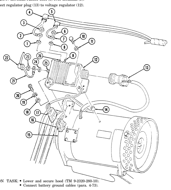
4-116. Control Box Terminal Block And Mounting Buss Replacement
This task covers: INITIAL SETUP: Applicable Models M996, M996A1, M997, M997A1, M997A2 Tools General mechanic's tool kit: automotive (Appendix B, Item 1) Materials/Parts Ten plain-assembled nuts (Appendix G, Items 201)
a. Removal b. Installation
Manual References TM 9-2320-280-24P Equipment Condition Control box removed (para. 4-96 or 4-97).
- Prior to removal, tag leads for installation. - M996 and M996A1 require only nine screws and leads.
a. Removal 1. Remove ten screws (6) and leads (5) from terminal block (8). 2. Remove two plain-assembled nuts (3), two leads 790 (2) and 797 and 797A (11) from screws (12).
Discard plain-assembled nuts (3).
-
Remove four plain-assembled nuts (1), screws (12), terminal (8), and mounting buss (9) from control box (4). Discard four plain-assembled nuts (1).
-
Remove four plain-assembled nuts (10), screws (7), and terminal block (8) from mounting buss (9).
Discard plain-assembled nuts (10).
B. Installation
- Install terminal block (8) on mounting buss (9) with four screws (7) and plain-assembled nuts (10). 2. Install mounting buss (9) on control box (4) with four screws (12) and plain-assembled nuts (1). 3. Install two leads 790 (2) and 797 and 797A (11) with two screws (12) and plain-assembled nuts (3). 4. Install ten leads (5) to terminal block (8) with ten screws (6).
4-116. Control Box Terminal Block And Mounting Buss Replacement
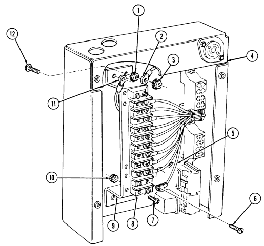
FOLLOW-ON TASK: Install control box (para. 4-96 or 4-97).
4-117. Control Box Fuse Block And Relay Socket Replacement
This task covers:
| INITIAL SETUP: |
|---|
| Applicable Models | Personnel Required |
|---|---|
| M1097, M1097A1, M1097A2 | One mechanic |
| One assistant | |
| Tools |
| Materials/Parts |
|---|
a. Removal b. Installation
General mechanic's tool kit: automotive (Appendix B, Item 1) Two tiedown straps (Appendix G, Item 308) Equipment Condition
-
Control box removed (para. 4-96 or 4-97). - If replacing a fuse block: remove fuses (TM 9-2320-280-10).
-
If replacing relay socket: remove relays (para. 4-120).
Procedures for replacing the upper fuse block, and relay socket are basically the same. This procedure covers replacement of the lower fuse block.
a. Removal 1. Remove two tiedown straps (3) from fuse block leads (7). Discard tiedown straps (3). 2. Remove two plain-assembled nuts (6), washers (5), and screws (2) from fuse block (4) and control box (1) and pull fuse block (4) away for access to leads (7). Discard plain-assembled nuts (6).
Prior to removal, tag leads for installation.
- Disconnect six leads (7) from fuse block (4) and remove fuse block (4).
b. Installation 1. Connect six leads (7) to fuse block (4). 2. Install fuse block (4) on control box (1) with two screws (2), washers (5), and plain-assembled nuts (6).
- Install fuse block leads (7) with two tiedown straps (3).
4-117. Control Box Fuse Block And Relay Socket Replacement (Cont'D)
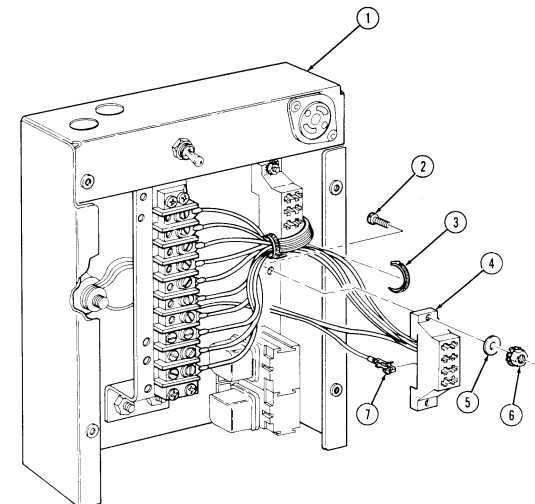
FOLLOW-ON TASKS: - If relay socket was replaced: install relays (para. 4-120).
- If fuse block was replaced: install fuses (TM 9-2320-280-10) · Install control box (para. 4-96 or 4-97).
4-118. Control Box Light Switch Replacement
This task covers: INITIAL SETUP:
| Applicable Models |
|---|
M996, M996A1, M997, M997A1, M997A2 Tools General mechanic's tool kit: automotive (Appendix B, Item 1)
Materials/Parts
Four lockwashers (Appendix G, Item 136) Plain-assembled nut (Appendix G, Item 201)
| Manual References |
|---|
| TM 9-2320-280-10 |
| TM 9-2320-280-24P |
| Equipment Condition |
| - Battery ground cable disconnected (para. 4-73). |
a. Removal b. Installation
a. Removal 1. Remove four screws (9), lockwashers (8), and cover (7) from control box (2). Discard lockwashers (8).
Prior to removal, tag leads for installation.
B. Installation
-
Install five leads (12) on switch terminals (11) with five washers (13) and screws (14). 2. Install switch (10) on top panel (1) with nut (4). 3. Install lead 797/797A (5) on control box screw (3) with plain-assembled nut (6). 4. Install cover (7) to control box (2) with four lockwashers (8) and screws (9).
-
Remove plain-assembled nut (6) and lead 797/797A (5) from control box screw (3). Discard plainassembled nut (6).
-
Remove nut (4) from switch (10) and top panel (1) and pull switch (10) out from under panel (1) for access to leads (12).
-
Remove five screws (14) and washers (13) from leads (12) and switch terminals (11) and remove switch (10).
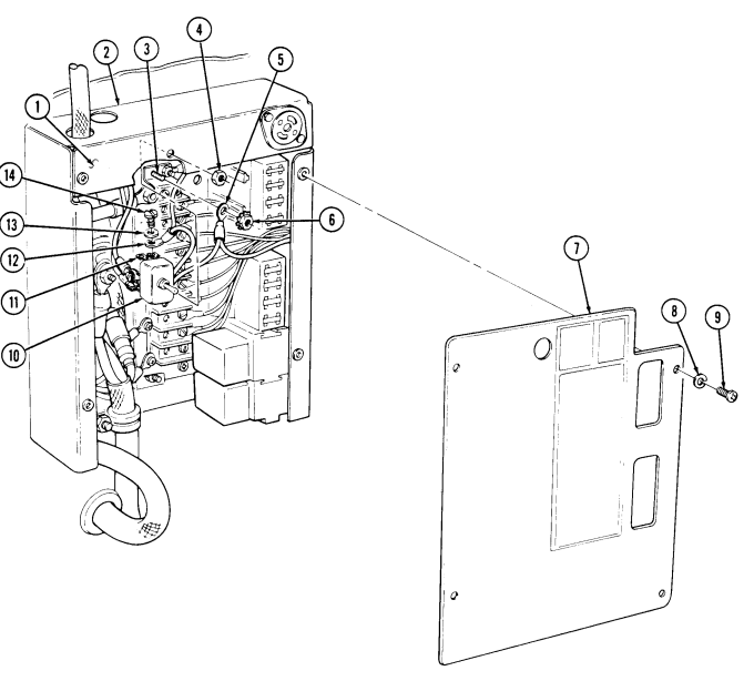
4-118. Control Box Light Switch Replacement (Cont'D)
FOLLOW-ON TASKS: - Connect battery ground cable (para. 4-73).
- • - Check operation of ambulance compartment lights (TM 9-2320-280-10).
4-119. Control Box Electrical Plug And Receptacle Replacement
| This task covers: |
|---|
| INITIAL SETUP: | |
|---|---|
| Applicable Models | Manual References |
| M997A2, M1025A2, M11035A2, M1043A2, | TM 9-2320-280-10 |
| M1045A2, M1097, M1097A1, M1097A2 | TM 9-2320-280-24P |
| Tools | Equipment Condition |
| General mechanic's tool kit: | - Battery ground cables disconnected (para. 4-73). |
| automotive (Appendix B, Item 1) | - Hood raised and secured (TM 9-2320-280-10). |
a. Plug Removal c. Receptacle Removal b. Plug Installation d. Receptacle Installation
a. Plug Removal 1. Turn and pull plug (4) from receptacle (3).
- Remove two screws (5) from plug (4). Open plug (4) and ensure positive (10), negative (12), and ground (11) leads for plug (4) are properly installed.
b. Plug Installation 1. Close plug (4) and install two screws (5) on plug (4).
- Insert plug (4) on receptacle (3).
c. Receptacle Removal
Note
For instructions on replacement of rivets, refer to para. 10-66.
- Remove two rivets (6) and receptacle (3) from control box (1). Pull receptacle (3) away for access to leads (2).
Note
Prior to removal, tag leads for installation.
-
Loosen screw (8) and push shield (9) away for access to leads (2).
-
Remove two screws (7), and leads (2) from receptacle (3).
d. Receptacle Installation 1. Install two leads (2) on receptacle (3) with two screws (7). Position shield (9) over screws (7) and tighten screw (8).
- Install receptacle (3) on control box (1) with two rivets (6).
4-119. Control Box Electrical Plug And Receptacle Replacement (Cont'D)
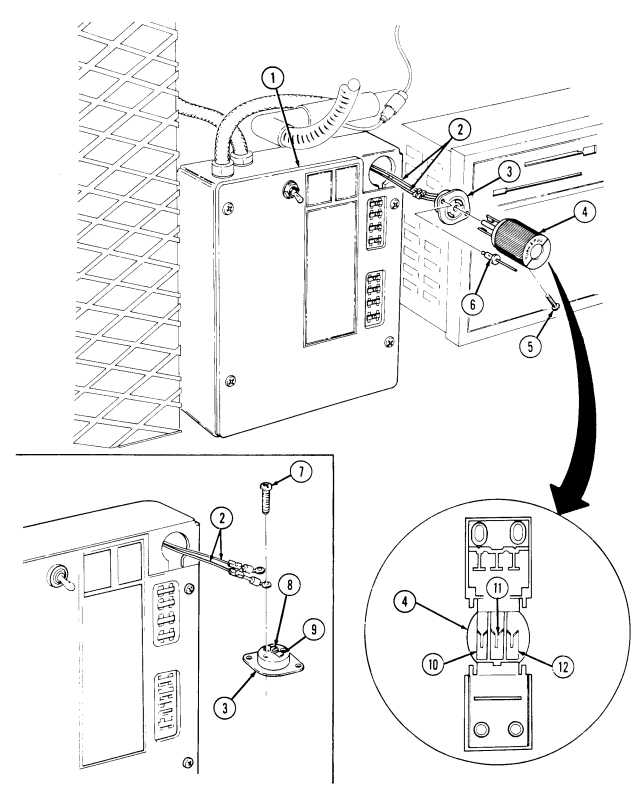
FOLLOW-ON TASK: Connect battery ground cable (para. 4-73).
4-120. Control Box Relay Replacement
This task covers: a. Removal b. Installation INITIAL SETUP: Applicable Models M996, M996A1, M997, M997A1, M997A2 Tools General mechanic's tool kit: automotive (Appendix B, Item 1) Materials/Parts Four lockwashers (Appendix G, Item 136) Manual References TM 9-2320-280-24P Equipment Condition Battery ground cable disconnected (para. 4-73). (receptacle only).
Prior to removal, tag leads for installation.
a. Removal 1. Remove four screws (3), lockwashers (4), and cover (2) from control box (1). Discard lockwashers (4). 2. Remove relay (6) from relay socket (5).
b. Installation 1. Install relay (6) in relay socket (5). 2. Install cover (2) on control box (1) with four lockwashers (4) and screws (3).
4-120. Control Box Relay Replacement (Cont'D)
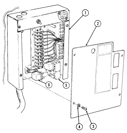
4-121. Condenser Fan/Pressure Switch Wiring Harness Replacement (M997, M997A1, M997A2)
This task covers: INITIAL SETUP: Applicable Models M997, M997A1, M997A2 Tools General mechanic's tool kit: automotive (Appendix B, Item 1) Materials/Parts Lockwasher (Appendix G, Item 182) a. Removal b. Installation Manual References TM 9-2320-280-24P Equipment Condition
- Battery ground cable disconnected (para. 4-73). - Air intake compartment panels removed (para. 11-184).
Prior to removal, tag leads for installation.
a. Removal b. Installation 1. Disconnect leads 436A (12) and 436B (13) from low pressure switch leads (11). 2. Remove nut (5), washer (4), capscrew (19), lockwasher (18), washer (17), and clamp (3) from harness (2) and dryer panel (20). Discard lockwasher (18).
-
Disconnect leads 436A (7), 436C (8), 799J (9), and 437A (10) from control box leads (6). 4. Disconnect leads 436B (15) and 436C (16) from high pressure switch leads (14). 5. Disconnect leads 437C (25), 799L (26), 437B (23), and 799K (24) from condenser fan leads (27) and (1).
-
Remove grommet (21) from condenser panel (22) and remove harness (2).
-
Install leads 799L (26), 437C (25), 437B (23), and 799K (24) through condenser panel (22) and connect to condenser fan leads (1) and (27).
-
Install grommet (21) on harness (2) and condenser panel (22). 3. Connect leads 436A (7), 436C (8), 799J (9), and 437A (10) to control box leads (6). 4. Connect leads 436B (15) and 436C (16) to high pressure switch leads (14). 5. Connect leads 436A (12) and 436B (13) to low pressure switch leads (11). 6. Install clamp (3) on harness (2) and dryer panel (20) with washer (17), lockwasher (18), capscrew (19), washer (4), and nut (5).
4-121. CONDENSER FAN/PRESSURE SWITCH WIRING HARNESS REPLACEMENT
(M997, M997A1, M997A2) (Cont'D)
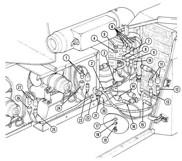
FOLLOW-ON TASKS: - Install air intake compartment panels (para. 11-184).
· Connect battery ground cable (para. 4-73).
4-122. Compressor/Heater Fuel Pump Wiring Harness Replacement (M997, M997A1, M997A2)
This task covers: a. Removal b. Installation INITIAL SETUP: Applicable Models M997, M997A1, M997A2 Tools General mechanic's tool kit: automotive (Appendix B, Item 1)
Materials/Parts
Two lockwashers (Appendix G, Item 133) Two locknuts (Appendix G, Item 70) Lockwasher (Appendix G, Item 178) Two assembled locknuts (Appendix G, Item 131) Two tiedown straps (Appendix G, Item 308) a. Removal
Manual References
TM 9-2320-280-24P Equipment Condition
- Passenger seat back removed (para. 10-45). - Heater fuel pump removed (para. 11-194).
Prior to removal, tag leads for installation.
-
Disconnect harness leads (1) from control box leads 436D (3) and 723B (2). 2. Remove capscrew (4), lockwasher (5), washer (6), and clamp (7) from AC line clamp (8) and body (9). Discard lockwasher (5).
-
Remove six screws (10), clamps (11), and harness (12) from body (9) and "B'' beam (13). 4. Deleted. 5. Remove grommet (16) from harness (12) and tunnel (17). 6. Remove locknut (32), washer (31), screw (27), and clamp (28) from fuel line clamp (29), body bracket (30) and harness. Discard locknut (32).
-
Remove locknut (22), washer (23), capscrew (33), and washer (23) from harness ground (34) and fuel pump (26). Discard locknut (22).
-
Remove nut (21) and lockwasher (20), and ground terminal (19) from ground stud (18). Discard lockwasher (20).
-
Disconnect harness lead (24) from fuel pump lead (25).
-
Remove screw (35) and clamp (36) from harness (12) and body (9).
4-122. COMPRESSOR/HEATER FUEL PUMP WIRING HARNESS REPLACEMENT (M997, M997A1 , M997A2) (Cont'd)
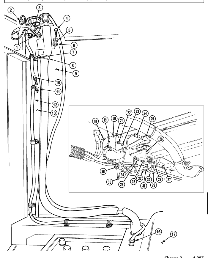
4-122. Compressor/Heater Fuel Pump Wiring Harness Replacement (M997, M997A1, M997A2) (Cont'D)
- Remove assembled locknut (2) and clamp (3) from harness (4) and starter cable bracket screw (1).
Discard assembled locknut (2).
-
Remove tiedown strap (6) from harness (4) and starter positive cable (5). Discard tiedown strap (6). 13. Remove screw (18) and assembled locknut (15) and clamp (17) from harness (4) and compressor bracket (16). Discard assembled locknut (15).
-
Remove nut (11), lockwasher (12), washer (19), capscrew (20), and clamp (13) from harness (4) and compressor (14). Discard lockwasher (12).
-
Disconnect harness leads (10) from leads (21). 16. Remove tiedown strap (9) from inside protective shield (8). Discard tiedown strap (9). 17. Remove harness (4) by routing through tunnel (7) and starter cable protective shield (8).
B. Installation
-
Route harness (4) through protective shield (8) and tunnel (7), and place in approximate mounting location.
-
Secure harness (4) with tiedown strap (9) inside of protective shield (8). 3. Connect harness leads (10) to leads (21). 4. Install clamp (13) on harness (4) and compressor (14) with washer (19), capscrew (20), lockwasher (12), and nut (11).
-
Install clamp (17) on harness (4) and compressor bracket (16) with screw (18) and assembled locknut (15).
-
Install clamp (3) on harness (4) and starter cable bracket screw (1) with assembled locknut (2). 7. Secure harness (4) to starter positive cable (5) with tiedown strap (6).
4-122. COMPRESSOR/HEATER FUEL PUMP WIRING HARNESS REPLACEMENT (M997, M997A1, M997A2) (Cont'd)
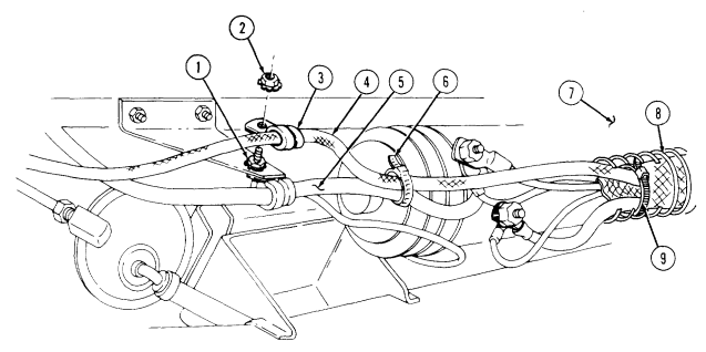
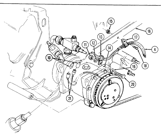
4-122. Compressor/Heater Fuel Pump Wiring Harness Replacement
(M997, M997A1, M997A2) (Cont'D)
-
Install clamp (21) on harness (17) and body rail (7) with screw (20). 9. Connect harness lead (8) to fuel pump lead (9).
-
Install harness ground terminal (2) on ground stud (1) with lockwasher (3) and nut (4). 11. Install harness ground (19) on fuel pump (10) with washer (6), capscrew (18), washer (6), and locknut (5).
-
Install clamp (12) on harness (17) and install clamp (12) and fuel line clamp (13) on body bracket (14) with screw (11), washer (15), and locknut (16).
-
Connect harness leads (22) to control box leads 436D (24) and 723B (23). 14. Install six clamps (31) on harness (17) and body (7) with six screws (30). 15. Install clamp (28) on harness (17), AC line clamp (29), and body (7) with washer (27), lockwasher (26), and capscrew (25).
-
Deleted. 17. Install grommet (34) on tunnel (35) and harness (17).
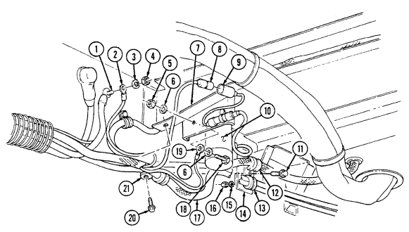
4-122. COMPRESSOR/HEATER FUEL PUMP WIRING HARNESS REPLACEMENT (M997, M997A1, M997A2) (Cont'd)
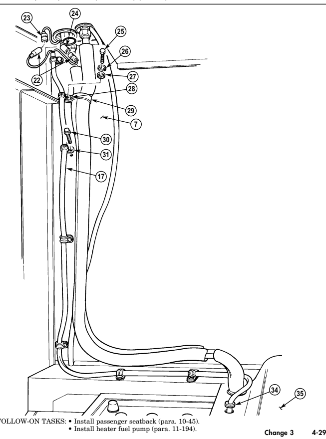
4-123. Heater/Vent System Control Box And Wiring Harness Replacement
This task covers:
Initial Setup:
Applicable Models M996, M996A1 Tools General mechanic's tool kit: automotive (Appendix B, Item 1)
Materials/Parts
Two locknuts (Appendix G, Item 70) Plain-assembled nut (Appendix G, Item 201) Plug button (Appendix G, Item 8) Four lockwashers (Appendix G, Item 136) Tiedown strap (Appendix G, Item 308) a. Removal b. Installation Manual References TM 9-2320-280-24P Equipment Condition Blower assembly removed (para. 11-212).
a. Removal
Prior to removal, tag leads for installation.
-
Remove locknut (1), washer (2), capscrew (8), washer (7), ground terminal (6), and capacitor (5) from fuel pump (16) and bracket (17). Discard locknut (1).
-
Disconnect control box lead (3) from fuel pump lead (4). 3. Remove locknut (15), washer (14), capscrew (11), and clamp (9) from control box harness (10), fuel line clamp (13), and body bracket (12). Discard locknut (15).
-
Remove grommet (18) from tunnel (26) and harness (10) and route harness (10) through hole in tunnel (26) and battery box grommet (25) into stowage compartment.
-
Remove two screws (22) and clamps (19) from harness (10), resuscitator harness (23), and body (21). 6. Remove tiedown strap (24) from harness (10) and resuscitator harness (23). Discard tiedown strap (24).
-
Route harness (10) up through grommet (20) into patient compartment.
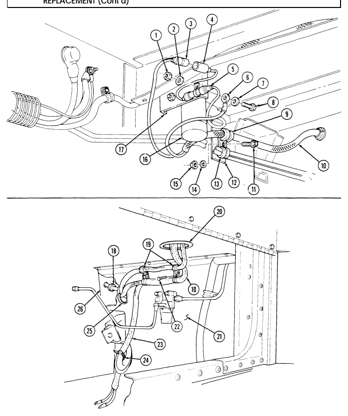
4-123. HEATER/VENT SYSTEM CONTROL BOX AND WIRING HARNESS REPLACEMENT (Cont'd)
4-123. Heater/Vent System Control Box And Wiring Harness
Replacement (Cont'D)
-
Remove three screws (20), clamps (21), harness (2), and battery cable harness (22) from body (5). 9. Remove four screws (19), lockwashers (18), and cover (17) from circuit box (4). Discard lockwashers (18).
-
Remove plain-assembled nut (16) and clamp (15) from harness (2) and screw (24). Discard plainassembled nut (16).
-
Remove three screws (14) from harness leads (13) and terminal block (25). 12. Remove three screws (12), clamps (11), and harness (2) from NBC harness (10) and body (5). 13. Remove two screws (9), washers (8), retainer (7) and grommet (6 ) from body (5) and harness (2). 14. Route harness (2) through grommet (6) hole in body (5). 15. Remove five screws (28) and clamps (29) from harness (2) and body (5). 16. Remove three nuts (33), lockwashers (34), capscrews (36), and clamps (35) from harness (2) and body (5). Discard lockwashers (34).
-
Disconnect plug (27) from heater receptacle (26). 18. Remove plug button (30) and control lever linkage (31) from duct door arm (32). Discard plug button (30).
-
Remove four screws (23), control box (1), and harness (2) from body (5).
B. Installation
-
Route harness (2) through control box opening (3) in body (5) and install control box (1) on body (5) with four screws (23).
-
Attach control lever linkage (31) to duct door arm (32) with plug button (30). 3. Install three clamps (35) on harness (2) and body (5) with capscrews (36), lockwashers (34), and nuts (33).
-
Connect control box plug (27) to heater receptacle (26). 5. Route harness (2) through grommet (6) hole in body (5). 6. Install five clamps (29) on harness (2) and body (5) with five screws (28). 7. Install three harness leads (13) to terminal block (25) with three screws (14). 8. Install clamp (15) on harness (2) and screw (24) with plain-assembled nut (16). 9. Install grommet (6) and retainer (7) on harness (2) and body (5) with two washers (8) and screws (9).
-
Install harness (2) in three clamps (11) with NBC harness (10), on body (5) with three screws (12). 11. Install cover (17) on circuit box (4) with four lockwashers (18) and screws (19). 12. Install harness (2) in three clamps (21) with battery cable harness (22), on body (5) with three screws (20).
4-123. HEATER/VENT SYSTEM CONTROL BOX AND WIRING HARNESS REPLACEMENT (Cont'd)
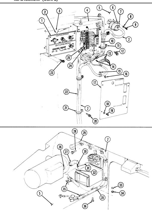
4-123. Heater/Vent System Control Box And Wiring Harness Replacement (Cont'D)
-
Route harness (21) down through grommet (20) into body (22) through battery box grommet (26) and through hole in tunnel (27).
-
Connect control box lead (3) to fuel pump lead (4). 15. Install fuel pump (16), capacitor (5), and ground terminal (6) on bracket (17) with washer (7), capscrew (8), washer (2), and locknut (1).
-
Install clamp (9) on harness (10) and install clamp (9) and clamp (13) on body bracket (12) with capscrew (11), washer (14), and locknut (15).
-
Install grommet (18) on harness (21) and into tunnel (27).
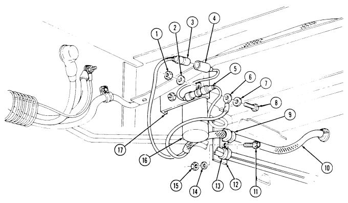 18. Install harness (21) in two clamps (19) on body (22) with two screws (23). 19. Install harness (21) on resuscitator harness (24) with tiedown strap (25).
4-123. HEATER/VENT SYSTEM CONTROL BOX AND WIRING HARNESS
Replacement (Cont'D)
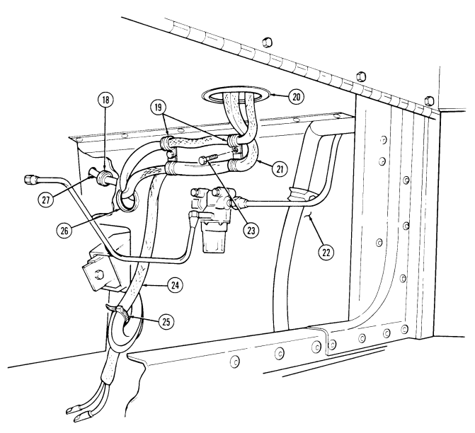
FOLLOW-ON TASK: Blower assembly installed (para. 11-212).
4-124. Nbc Control Panel Replacement
This task covers: INITIAL SETUP:
| Tools |
|---|
| Materials/Parts |
|---|
| Applicable Models |
|---|
M996, M996A1, M997, M997A1, M997A2
| Equipment Condition |
|---|
| - Control box removed (para. 4-96 or 4-97). |
| - If replacing a fuse block: remove fuses |
| (TM 9-2320-280-10). |
| - If replacing relay socket: remove relays |
| (para. 4-120). |
General mechanic's tool kit: automotive (Appendix B, Item 1) Five lockwashers (Appendix G, Item 169) Lockwasher (Appendix G, Item 134) Four plain-assembled nuts (Appendix G, Item 201)
a. Removal b. Installation
a. Removal
| Manual References |
|---|
| TM 9-2320-280-10 |
| TM 9-2320-280-24P |
M996 ambulance will not have cushioned wire clamp on ceiling.
1.Remove screw (3) from cushioned wire clamp (4) and passenger ceiling (2). 2.Remove six screws (1) from NBC control panel (5) and ambulance body (6). 3.Remove two plain-assembled nuts (8) and screws (7) from two cushioned wire clamps (9). Discard plain-assembled nuts (8).
Prior to removal, tag all leads for installation.
4.Remove two screws (10), lockwashers (11), and leads 783 (13) and 783A (12) from NBC control panel ON/OFF toggle switch (14). Discard lockwashers (11).
4-124. Nbc Control Panel Replacement (Cont'D)
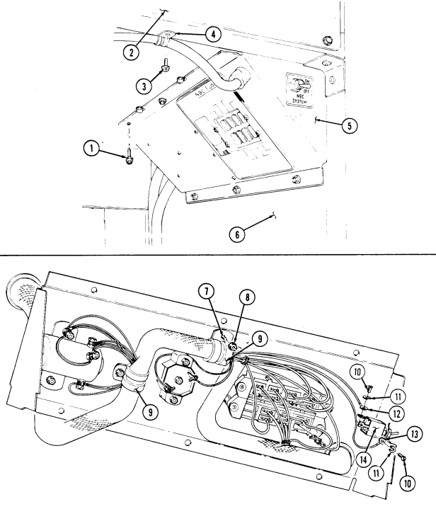
4-124. Nbc Control Panel Replacement (Cont'D)
-
Remove two screws (12), lockwashers (13), and leads 782A (14) and 783 (16) from NBC control panel circuit breaker (15). Discard lockwashers (13).
-
Remove plain-assembled nut (11), diode (24), and leads 783A (17) and 783B (18) from NBC control panel relay (19). Discard plain-assembled nut (11).
M996 and M996A1 ambulances have three leads, 785, 786, and 787, on NBC control panel relay.
-
Remove nut (5), lockwasher (6), and leads 784 (7), 787 (8) 785 (9), and 786 (10) from NBC control panel relay (19). Discard lockwasher (6).
-
Remove nut (22), lockwasher (23), and leads 782 (21) and 782A (20) from NBC control panel relay (19). Discard lockwasher (23).
-
Remove plain-assembled nut (25), leads 795 (3), 796 (4), and 793 (2), and diode (24) from NBC control panel relay ground (1). Discard plain-assembled nut (25).
Use care when removing lead clips from NBC control panel fuse block to prevent damage to leads, wire clips, and/or fuse block.
-
For M997, M997A1 and M997A2 ambulances, perform steps 10 through 16 for removal of leads from NBC fuse block.
-
For M996 and M996A1 ambulances, perform steps 17 through 21 for removal of leads from NBC fuse block.
-
Leads 787, 784, and 786 have two way jumpers connecting fuses for heaters 4 & 5, 6 & 7, and 2 & 3 respectively.
- Remove leads 787B (26) and 787 (8) from NBC fuse block (31) for heater fuse #4. 11. Remove lead 787A (27) from NBC fuse block (31) for heater fuse #5. 12. Remove leads 784 (30) and 784B (28) from NBC fuse block (31) for heater fuse #6. 13. Remove lead 784A (29) from NBC fuse block (31) for heater fuse #7. 14. Remove leads 785A (9) and 785 (34) from NBC fuse block (31) for heater fuse #1. 15. Remove lead 786A (33) from NBC fuse block (31) for heater fuse #2. 16. Remove lead 786 (32) and lead 786B (10) from NBC fuse block (31) for heater fuse #3.
4-124. Nbc Control Panel Replacement (Cont'D)
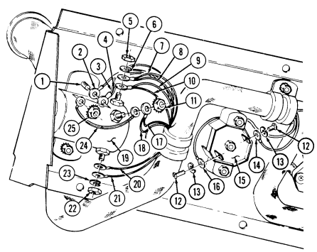
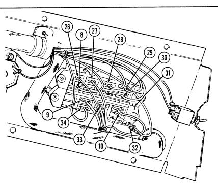
4-124. Nbc Control Panel Replacement (Cont'D)
Leads 785 and 786 have two way jumpers connecting fuses for heaters 1 & 2 and 3 & 4 respectively.
-
Remove leads 785 (3) and 785A (9) from NBC fuse block (5) for heater fuse #1.
-
Remove lead 785B (8) from NBC fuse block (5) for heater fuse #2. 19. Remove leads 786 (4) and 786A (7) from NBC fuse bock (5) for heater fuse #3. 20. Remove lead 786B (6) from NBC fuse block (5) for heater fuse #4.
-
Remove leads 787 (1) and 787A (2) from NBC fuse block (5) for heater fuse #5.
4-124. Nbc Control Panel Replacement (Cont'D)
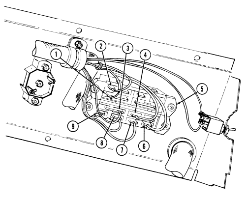
4-124. Nbc Control Panel Replacement (Cont'D)
b. Installation
Use care when installing leads to NBC control panel fuse block. Ensure lead clips lock into place. Failure to do so may cause damage to equipment and/or injury to personnel.
- Install two cushioned wire clamps (17) with wire harness (14) in place onto NBC control panel (12) with screws (15) and plain-assembled nuts (16).
-
For M997, M997A1 and M997A2 ambulances, perform steps 8 through 14 for installation of leads to NBC fuse block.
-
For M996 and M996A1 ambulances, perform steps 15 through 19 for installation of leads to NBC fuse block.
-
Leads 787, 784, and 786 have two way jumpers connecting fuses for heaters 4 & 5, 6 & 7, and 2 & 3 respectively.
- Install leads 795 (3), 796 (4) and lead 793 (2), and diode (28) onto NBC control panel relay ground (1) with plain-assembled nut (29).
M996 and M996A1 ambulances have three leads, 785, 786, and 787, secured to NBC control panel relay.
-
Install leads 784 (7), 787 (8), and leads 785 (9), 786 (10) onto NBC control panel relay (24) with nut (5) and lockwasher (6).
-
Install leads 783A (22) and 783B (23) and remaining lead from diode (28) onto NBC control panel relay (24) with plain-assembled nut (11).
-
Install leads 782 (25) and 782A (20) onto NBC control panel relay (24) with nut (26) and lockwasher (27).
-
Install leads 782A (20) and 783 (21) onto NBC control panel circuit breaker (13) with two screws (18) and lockwashers (19).
-
Install leads 783 (21) and 783A (22) onto NBC control panel ON/OFF toggle switch (35) with two screws (33) and lockwashers (34).
-
Install leads 787B (30) and 787 (8) into NBC fuse block (40) for heater fuse #4. 9. Install lead 787A (31) into NBC fuse block (40) for heater fuse #5.
-
Install lead 784B (32) into NBC fuse block (40) for heater fuse #6. 11. Install lead 784A (36) and 784 (7) into NBC fuse block (40) for heater fuse #7. 12. Install leads 785 (9) and 785A (39) into NBC fuse block (40) for heater fuse #1. 13. Install leads 786 (10) and 786B (38) into NBC fuse block (40) for heater fuse #2. 14. Install lead 786A (37) into NBC fuse block (40) for heater fuse #3.
4-124. Nbc Control Panel Replacement (Cont'D)
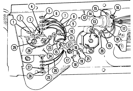
ੇ
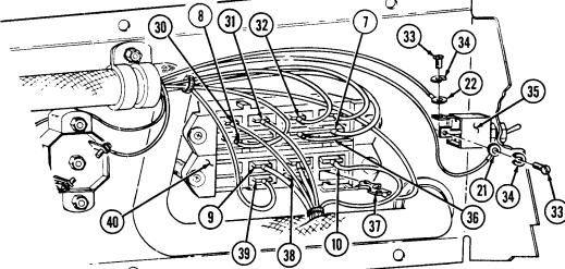
Q
4-124. Nbc Control Panel Replacement (Cont'D)
Note
Leads 785 and 786 have two way jumpers connecting fuses for heaters 1 & 2 and 3 & 4 respectively.
- Install leads 787 (1) and 787A (2) on NBC fuse block (5) for heater fuse #5.
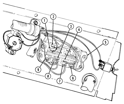 16. Install lead 786B (6) on NBC fuse block (5) for heater fuse #4. 17. Install leads 786 (4) and 786A (7) on NBC fuse block (5) for heater fuse #3. 18. Install lead 785A (9) on NBC fuse block (5) for heater fuse #2. 19. Install leads 785 (3) and 785B (8) on NBC fuse block (5) for heater fuse #1.
4-124. Nbc Control Panel Replacement (Cont'D)
- Install NBC control panel (13) on ambulance body (14) with six screws (15).
NOTE M996 and M996A1 ambulances will not have cushioned wire
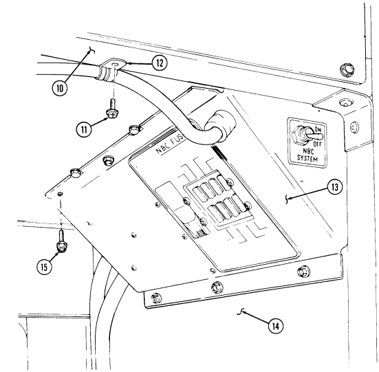
clamp on ceiling.
- Install cushioned wire clamp (12) on passenger ceiling (10) with screw (11).
FOLLOW-ON TASKS: Install NBC wiring harness: M996 and M996A1 (para. 4-99) M997, M997A1 and M997A2 (para. 4-100).
Install NBC control panel fuses (TM 9-2320-280-10). Install battery ground cable to battery (para. 4-73).
4-125. Heat/Vent Control Panel Removal (M996, M996A1)
This task covers: a. Removal b. Installation INITIAL SETUP: Applicable Models M996, M996A1 Tools General mechanic's tool kit: automotive (Appendix B, Item 1) Materials/Parts Plug button (Appendix G, Item 8) Manual References TM 9-2320-280-24P Equipment Condition
- Battery ground cable disconnected (para. 4-73). - Heater compartment panel removal (para. 11204).
a. Removal 1. Remove plug button (1) from control arm (2) and blower duct arm (5). Discard plug button (1). 2. Disconnect vent door control arm (3) from switch lever assembly (4). 3. Remove four screws (7), control panel (8), and control arm (2) from body (6).
b. Installation 1. Connect control arm (2) to switch lever assembly (4) and install control panel (8) on body (6) with four screws (7).
- Connect vent door control arm (3) to switch lever assembly (4).
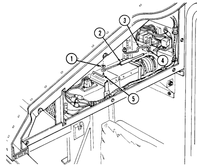 3. Install control arm (2) on blower duct arm (5) with plug button (1).
4-125. Heat/Vent Control Panel Removal (M996, M996A1) (Cont'D)
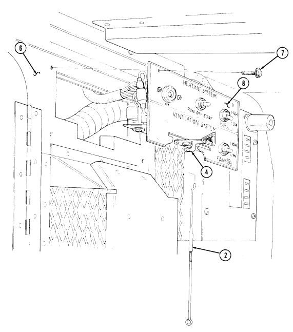
FOLLOW-ON TASKS: .
Connect battery ground cable (para. 4-73). Install heater compartment panel (para. 11-204).
4-126. Heat/Vent Control Panel Relay And Switch Maintenance (M996, M996A1)
This task covers: a. Heater Run-Start Switch Removal i. Spot Vent Switch Removal b. Heater Run-Start Switch Installation j. Spot Vent Switch Installation c. 24-Volt Relay Removal k. Fuel Hi-Low Switch Removal d. 24-Volt Relay Installation l. Fuel Hi-Low Switch Installation e. Relay Socket Removal m. Fan Hi-Low Switch Removal f. Relay Socket Installation n. Fan Hi-Low Switch Installation g. Heat On Light Removal o. Rollover Switch Removal h. Heat On Light Installation p. Rollover Switch Installation
Initial Setup:
Applicable Models M996, M996A1 Tools General mechanic's tool kit: automotive (Appendix B, Item 1)
Manual References
TM 9-2320-280-24P
Equipment Condition
-
Battery ground cable disconnected (para. 4-73). - Heater compartment panel removed (para. 11-204).
-
Heat/vent control panel removed (para. 4-125).
Prior to removal, tag leads for installation.
A. Heater Run-Start Switch Removal
- Remove nut (8), switch (4), washer (6), and nut (5) from panel (7). 2. Remove six screws (1), lockwashers (3), and seven terminals (2) from switch (4). Discard lockwashers (3).
B. Heater Run-Start Switch Installation
- Install seven terminals (2) on switch (4) with six lockwashers (3) and screws (1). 2. Install nut (5), washer (6), and switch (4) on panel (7) with nut (8).
Materials/Parts Twenty lockwashers (Appendix G, Item 169) Three plain-assembled nuts (Appendix G, Item 201) 4-126. HEAT/VENT CONTROL PANEL RELAY AND SWITCH MAINTENANCE
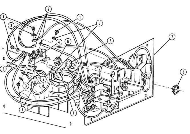
4-126. HEAT/VENT CONTROL PANEL RELAY AND SWITCH MAINTENANCE (M996, M996A1) (Cont'd) c. 24-Volt Relay Removal Remove 24-volt relay (1) from relay mounting socket (2).
d. 24-Volt Relay Installation Install 24-volt relay (1) on relay mounting socket (2).
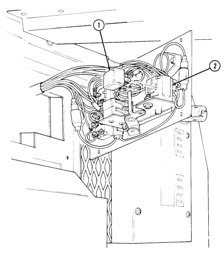
4-126. Heat/Vent Control Panel Relay And Switch Maintenance (M996, M996A1) (Cont'D)
e. Relay Socket Removal 1. Remove screw (3), washer (2), plain-assembled nut (7), and relay mounting socket (4) from mounting bracket (6). Discard plain-assembled nut (7).
- Remove 24-volt relay (1) and five terminals (5) from relay mounting socket (4).
f. Relay Socket Installation 1. Install five terminals (5) and 24-volt relay (1) on relay mounting socket (4). 2. Install relay mounting socket (4) on bracket (6) with screw (3), washer (2), and plain-assembled nut (7).
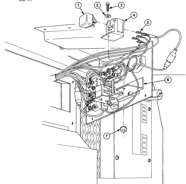
4-126. Heat/Vent Control Panel Relay And Switch Maintenance (M996, M996A1) (Cont'D)
g. Heat On Light Removal 1. Remove screw (7), lockwasher (8), terminal (9), and light terminal (6) from heater HI-LOW switch (10).
Discard lockwasher (8).
- Disconnect light lead (2) from relay lead (5). Remove two screws (4) and light (1) from panel (3).
H. Heat On Light Installation
-
Install light (1) on panel (3) with two screws (4). Connect relay lead (5) to light lead (2).
-
Install light terminal (6) and terminal (9) on HI-LOW switch (10) with lockwasher (8) and screw (7).
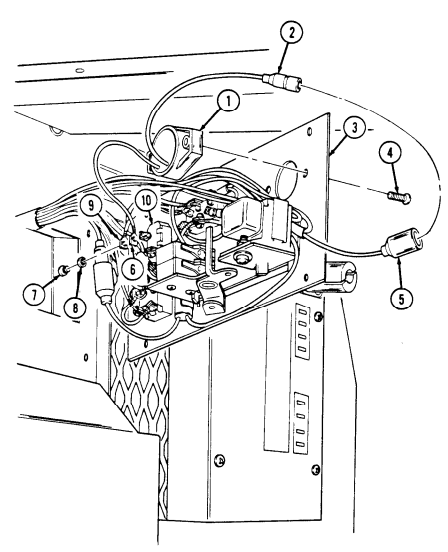
4-126. Heat/Vent Control Panel Relay And Switch Maintenance (M996, M996A1) (Cont'D)
i. Spot Vent Switch Removal 1. Remove two screws (6), washers (5.1), plain-assembled nuts (3), and switch (4) from lever bracket (7). Discard plain-assembled nuts (3).
- Remove four screws (1), lockwashers (2), and terminals (5) from switch (4). Discard lockwashers (2).
j. Spot Vent Switch Installation 1. Install four terminals (5) on switch (4) with lockwashers (2) and screws (1). 2. Install switch (4) on lever bracket (7) with two screws (6), washers (5.1), and plain-assembled nuts (3).
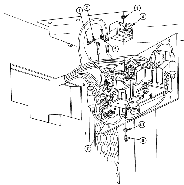
4-126. Heat/Vent Control Panel Relay And Switch Maintenance
(M996, M996A1) (Cont'd)
-
Remove nut (5), switch (1) washer (3) and nut (2) from panel (4).
-
Remove two screws (7), lockwashers (8) and three terminals (6) from switch (1). Discard lockwashers (8).
-
Install three terminals (6) on switch (1) with two lockwashers (8) and screws (7).
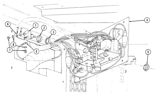 2. Install nut (2), washer (3), and switch (1) on panel (4) with nut (5).
4-126. Heat/Vent Control Panel Relay And Switch Maintenance (M996, M996A1) (Cont'D)
m. Fan Hi-Low Switch Removal 1. Remove nut (5), switch (4), washer (7), and nut (8) from panel (6).
- Remove six screws (3), lockwashers (1) and six terminals (2) from switch (4). Discard lockwashers (1).
n. Fan Hi-Low Switch Installation 1. Install six terminals (2) on switch (4) with six lockwashers (1) and screws (3).
- Install nut (8), washer (7), and switch (4) on panel (6) with nut (5).
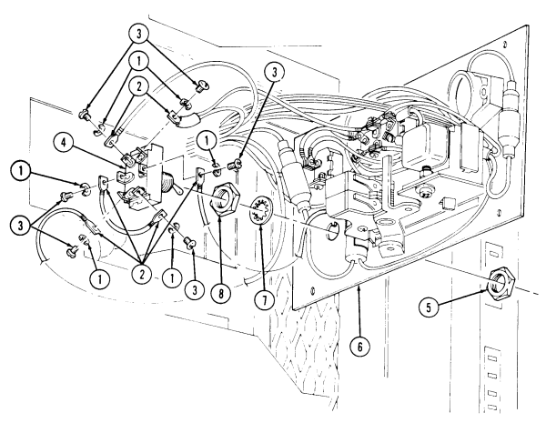
4-126. Heat/Vent Control Panel, Relay And Switch Maintenance (M996, M996A1) (Cont'D)
O. Rollover Switch Removal
-
Disconnect rollover switch lead (7) from harness lead (8).
-
Remove screw (4) and lockwasher (3) from two terminals (2) and heater RUN-START switch (5) and remove rollover switch (1). Discard lockwasher (3).
P. Rollover Switch Installation
- Install two terminals (2) on heater RUN-START switch (5) with lockwasher (3) and screw (4).
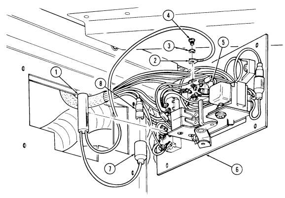
- Connect harness lead (8) to rollover switch lead (7) and snap in rollover switch (1) in switch bracket (6).
FOLLOW-ON TASKS: Install heat/vent control panel (para. 4-125).
Install heater compartment panel (para. 11-204). Connect battery ground cable (para. 4-73).
4-127. Heat/Air-Conditioning Control Panel Relay And Switch Maintenance (M997, M997A1, M997A2)
This task covers: a. Heat A/C Panel Removal h. Fuel Hi-Low Switch Installation b. Heat A/C Panel Installation i. Fan Hi-Low Switch Removal c. Heater Run-Start Switch Removal j. Fan Hi-Low Switch Installation d. Heater Run-Start Switch Installation k. A/C On-Off Switch Removal e. Heat On Light Removal l. A/C On-Off Switch Installation f. Heat On Light Installation m. Rollover Switch Removal g. Fuel Hi-Low Switch Removal n. Rollover Switch Installation INITIAL SETUP: Applicable Models M997, M997A1, M997A2 Tools General mechanic's tool kit: automotive (Appendix B, Item 1) Materials/Parts Nine lockwashers (Appendix G, Item 169) Two lockwashers (Appendix G, Item 138) Manual References TM 9-2320-280-24P Equipment Condition Battery ground cable disconnected (para. 4-73).
A. Heat A/C Control Panel Removal
Remove four screws (1), two bolts (6), lockwashers (5) and panel (2) from harness bracket (4) and control box (3). Pull panel (2) away from control box (3). Discard lockwashers (5).
b. Heat A/C Control Panel Installation
Check for loose or disconnected wires before installing panel.
Install panel (2) on harness bracket (4) and control box (3) with two lockwashers (5), bolts (6), and four screws (1).
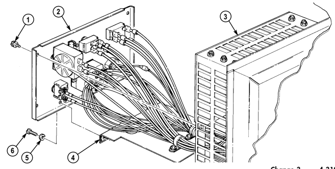
4-127. Heat/Air-Conditioning Control Panel Relay And Switch Maintenance (M997, M997A1, M997A2) (Cont'D)
Note
Prior to removal, tag leads for installation.
-
Remove two screws (1) and switch (6) from panel (2). 2. Remove six screws (4), lockwashers (5), and twelve terminals (3) from switch (6). Discard lockwashers (5).
-
Install twelve terminals (3) on switch (6) with six lockwashers (5) and screws (4).
-
Install switch (6) on panel (2) with two screws (1).
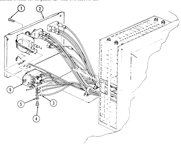
4-127. Heat/Air-Conditioning Control Panel Relay And Switch Maintenance (M997, M997A1, M997A2) (Cont'D)
Note
Prior to removal, tag leads for installation.
-
Remove screw (9), lockwasher (8), and light terminal (7) from heater run-start switch (6). Discard lockwasher (8).
-
Disconnect light lead (4) from relay lead (5) and remove two screws (1) and light (3) from panel (2).
-
Install light (3) on panel (2) with two screws (1) and connect relay lead (5) to light lead (4).
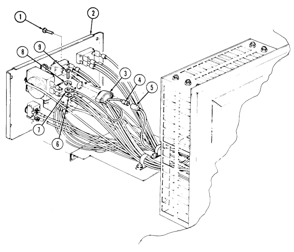
- Install light terminal (7) on heater run-start switch (6) with lockwasher (8) and screw (9).
4-127. Heat/Air-Conditioning Control Panel Relay And Switch Maintenance (M997, M997A1, M997A2) (Cont'D)
-
Remove nut (1), switch (6), washer (8), and nut (7) from panel (2). 2. Remove two screws (4), lockwashers (5), and terminals (3) from switch (6). Discard lockwashers (5).
-
Install two terminals (3) on switch (6) with two lockwashers (5) and screws (4).
Note Position toggle switch in low position.
- Install nut (7), washer (8), and switch (6) on panel (2) with nut (1).
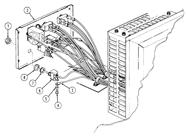
4-127. Heat/Air-Conditioning Control Panel Relay And Switch Maintenance (M997, M997A1, M997A2) (Cont'D)
Note
Prior to removal, tag leads for installation.
i. Fan Hi-Low Switch Removal 1. Remove nut (1), switch (5), washer (3), and nut (4) from panel (2).
- Pull four terminals (6) from switch (5) and remove switch (5).
j. Fan Hi-Low Switch Installation 1. Connect four terminals (6) to switch (5).
- Install nut (4), washer (3), and switch (5) on panel (2) with nut (1).
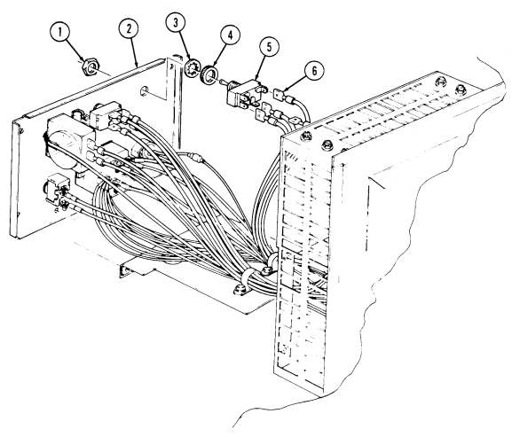
4-127. Heat/Air-Conditioning Control Panel Relay And Switch Maintenance [M997, M997A1, M997A2) (Cont'D)
Prior to removal, tag leads for installation.
-
Remove nut (1), switch (5), washer (3), and nut (4) from panel (2).
-
Pull four terminals (6) from switch (5) and remove switch (5).
-
Connect four terminals (6) to switch (5).
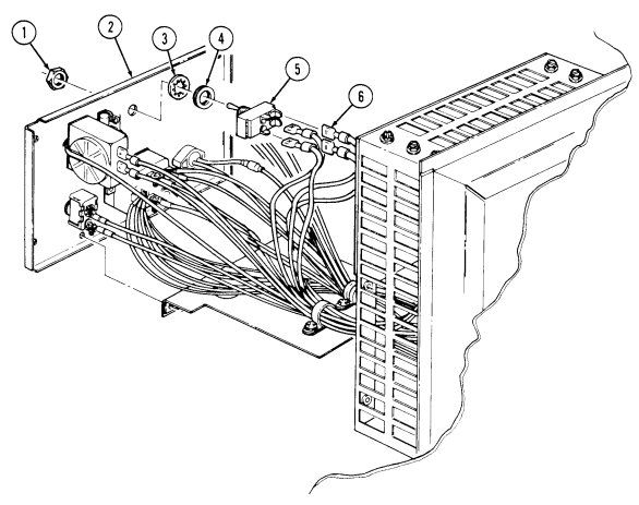 2. Install nut (4), washer (3), and switch (5) on panel (2) with nut (1).
4-127. Heat/Air-Conditioning Control Panel Relay And Switch Maintenance (M997, M997A1, M997A2) (Cont'D)
NOTE Prior to removal, tag leads for installation.
m. Rollover Switch Removal Disconnect two rollover switch leads (4) from harness leads (3) and pull rollover switch (2) out of switch bracket (1).
n. Rollover Switch Installation Connect two harness leads (3) to rollover switch leads (4) and snap in rollover switch (2) into
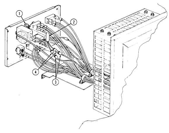
switch bracket (1).
FOLLOW-ON TASK: Connect battery ground cable (para. 4-73).